Small Basic - 3D Visualisation
Introduction
This blog is about a 3D visualisation extension that has been available in the LitDev extension for a few years now.
3D rendering can be complex, but once the basics of 2D movement, events and structured programming are mastered in Small Basic, the leap into 3D is not so great. I have tried to keep the number of methods in the LD3DView object as few as possible, while providing sufficient power to achieve impressive results.
The visualisation is rendered inside the GraphicsWindow like all other LD extension controls or shapes (using the AddView method), so the 3D visual region itself can be resized, moved or even rotated like any other shape. This allows you to add buttons or other controls inside the GraphicsWindow and use the GraphicsWindow mouse and key events.
3D in Small Basic is not going to achieve the performance or features of modern 3D games, but you can quickly gain an understanding of the ideas that are used in these games and with careful programming create immersive and very playable games or other applications.
Coordinates in 3D
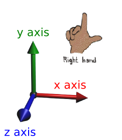
The space where objects in a 3D model exist is called the scene. It has 3 directions X, Y and Z that do not correspond to pixel positions. Like the 2D view in Small Basic X increases from left to right, but Y increases upwards, and Z increases from far to near. This is called a 'right handed system'.
Objects in the scene are positioned, scaled or rotated using world coordinates (X,Y,Z).
Rendering
What we actually see on our screen is not 3D, the screen is flat (2D) so the program has to work out what we see and display it for us. This is called rendering and depends on several things. While the maths of how this is actually done will help an understanding it is not essential.
Firstly we need objects positioned in the scene, we also need lights to see anything and we need to know where the observer is positioned and which direction they are looking.
Mathematically these occur in stages called the rending graphics pipeline. We will take a look at the main elements needed to render a scene in turn.
Objects
These are things we will see. They are described by vertices and elements.
The vertices are just points (X,Y,Z) defined in a local coordinates, and the elements are lists of vertices that are joined to form surfaces.
The local vertex coordinates are just describing the object, not where or how it is positioned within the scene. The centre of the object is defined to be at (0,0,0) in its local coordinates.
The order in which the vertices are listed determines the outer and inner surface of the object (i.e. the outward normal direction). This is not important when getting started but the renderer uses this information to not display hidden surfaces known as back face culling. The order or winding used is counter-clockwise for outer direction.
The simplest object is a triangle, but usually objects consist of many triangles called a mesh. Initially, the most difficult part of 3D programming is creating complex meshes, but there are many other software programs available to help create these.
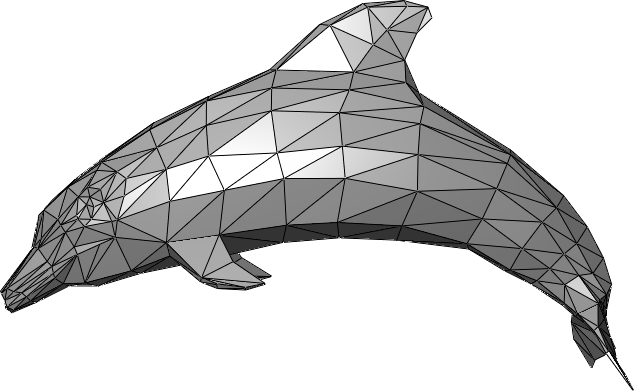
A typical mesh
In this extension, I have provided some methods (using a 3rd partly library HelixToolkit) to directly create the meshes for Spheres (AddSphere), Tubes (AddTube) and import meshes (LoadModel) from some popular file types. However, it is an important part of 3D programming to understand how meshes are formed so I have not abstracted mesh generation away in methods to just do it for you.
Pretty cool effects can be achieved with fairly simple meshes and I will show how to create a mesh for a cube using AddGeometry.
A mesh will often have additional properties like colour, image or how it reacts to light. A mesh with these properties is called a geometry.
There are several other methods to manipulate geometries, AddImage, ModifyObject, CloneObject, Freeze and ReverseNormals.
ReverseNormals sets the inside of the geometry to be visible instead of the outside. This can be used with a very large sphere or cube to create a horizon image in the distance of your world in all directions. This simple but very effective technique is called a skydome or skybox.
Lights
To see diffuse material geometries we need lights. Emissive materials don't require lights, they emit their own colours or images. Lights are just special objects positioned in the scene. There are several types of light, created using the methods AddAmbientLight, AddDirectionalLight, AddSpotLight and AddPointLight. All lights have a colour.
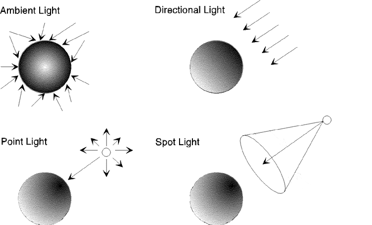
Ambient light
An ambient light lights all objects equally, we often set it to a low intensity (grey colour).
Directional light
A directional light fills the scene from one direction. It is assumed to be infinitely far away, and can be used for example like sunlight.
Spot light
A spotlight is also directional, but also has a position, limited lighting cone and range.
Point light
A point light is not directional, but does have a set position and limited range.
World transformations
This is the first step of the render pipeline.
Once we have an object geometry in local coordinates we can to transform it to world coordinates. This just means position it in the scene. So if we want 20 cubes, they can all have the same geometry, but are transformed differently into the scene.
There are 3 transformations; rotate, scale and translate.
Rotate
The rotate methods are RotateGeometry, RotateGeometry2 and AnimateRotation
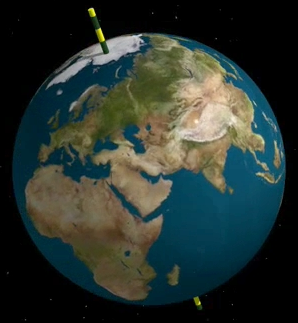
Rotate about the shape centre by an angle. The rotation is about an axis line, just like the earth rotating about its axis.
Scale
The scale method is ScaleGeometry.
This is just like zoom, but you can zoom in 3 directions.
Translate
The translate methods are TranslateGeometry and AnimateTranslation.
This is just like move, but you can move in 3 directions.
Camera
The second step of the render pipeline is to calculate how everything is lit and this depends on where the observer is and what direction they are looking.
The camera defines how the scene is observed.
The ResetCamera method sets the position, view direction as well as set the up direction, usually (0,1,0).
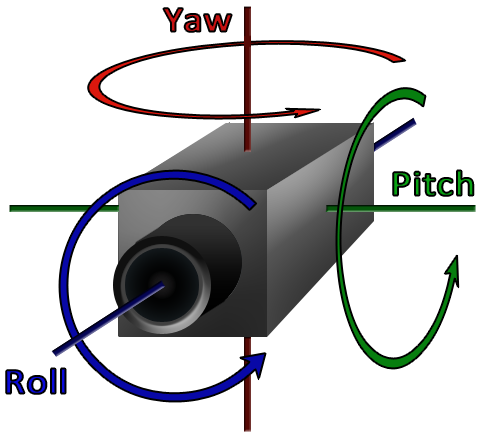
The MoveCamera method allows you to move forwards or backwards in the view direction, as well as turn the view direction using yaw, pitch and roll angles. Note that these can change the up direction.
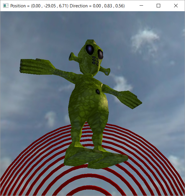
The methods GetCameraPosition and GetCameraDirection can be useful to determine where you are in the scene if the camera is being moved with MoveCamera.
Projection
The final step of the render pipeline is to transform the observed view to pixels that are displayed on screen.
Some camera options can affect this, such as the angle of view (like telephoto or wide angle lenses) which determines perspective. These properties are set using CameraProperties.
Geometries
As an example we create a cube. It has 8 vertices and 6 faces, with each face consisting of 2 triangles, so there are 12 triangular elements.
We want the centre of the cube to be at (0,0,0) and it is usual to make it with edges of unit length so it is easy to scale in world coordinates.
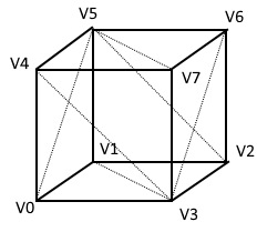
Therefore the vertex coordinates are:
- V0=(-0.5,-0.5,0.5)
- V1=(-0.5,-0.5,-0.5)
- V2=(0.5,-0.5,-0.5)
- V3=(0.5,-0.5,0.5)
- V4=(-0.5,0.5,0.5)
- V5=(-0.5,0.5,-0.5)
- V6=(0.5,0.5,-0.5)
- V7=(0.5,0.5,0.5)
The 2 face triangles on the bottom face (counter clockwise winding when viewed looking at the face) are indexed by 3 vertices.
- 0:1:3
- 1:2:3
Note that the vertices are indexed from 0. This is not normally how we do things in Small Basic, but since you may create index lists using external software I chose to stick to this convention in this case.
The other triangles are:
- 4:7:5 (top)
- 5:7:6 (top)
- 0:3:4 (front)
- 3:7:4 (front)
- 1:5:2 (back)
- 2:5:6 (back)
- 0:4:5 (left)
- 0:5:1 (left)
- 3:6:7 (right)
- 2:6:3 (right)
Materials
We can set a colour for the geometry and we can set whether it is emissive or diffusive. Emissive just shows the colour and diffusive requires lights to show the colour in combination with light colours.
The following code creates a LightBlue coloured diffusive cube.
Note the use of colon and space deliminators, rather than using arrays - this was to make it easier to create and add geometries in single lines since this is how you might obtain this data from external mesh generation software. I didn't use a comma deliminator since in some localisations this is interpreted as a decimal point.
vertices = "-0.5:-0.5:0.5 -0.5:-0.5:-0.5 0.5:-0.5:-0.5 0.5:-0.5:0.5 -0.5:0.5:0.5 -0.5:0.5:-0.5 0.5:0.5:-0.5 0.5:0.5:0.5"
indices = "0:1:3 1:2:3 4:7:5 5:7:6 0:3:4 3:7:4 1:5:2 2:5:6 0:4:5 0:5:1 3:6:7 2:6:3"
cube = LD3DView.AddGeometry(view,vertices,indices,"","LightBlue","D")
It is also possible to map one or more images onto a mesh and set emissive, diffusive and specular components separately. This requires setting texture coordinates to map the image onto the mesh.
A small example
We use the cube defined above and add some lights and keyboard movement control:
- animate a continual rotation for the cube
- add 4 directional coloured lights
- move the cube left, right, up and down with the arrow keys
- move the camera forwards and backwards with W and S keys
- yaw the camera left and right with A and D keys
'Create the GraphicsWindow
gw = 600
gh = 600
GraphicsWindow.Width = 600
GraphicsWindow.Height = 600
GraphicsWindow.BackgroundColor = "DarkBlue"
'
'Create the 3D scene
view = LD3DView.AddView(gw,gh,"True")
LD3DView.ResetCamera(view,0,0,8,0,0,-1,0,1,0)
LD3DView.AddDirectionalLight(view,"Red",1,0,1)
LD3DView.AddDirectionalLight(view,"Green",1,0,-1)
LD3DView.AddDirectionalLight(view,"Blue",-1,0,1)
LD3DView.AddDirectionalLight(view,"Yellow",-1,0,-1)
MakeCube()
LD3DView.AnimateRotation(view,cube,0,1,1,1,360,10,-1)
x = 0
y = 0
z = 0
'
'Game loop to handle user interaction
While ("True")
'Move cube
If (LDUtilities.KeyDown("Left")) Then
x = x-0.1
ElseIf (LDUtilities.KeyDown("Right")) Then
x = x+0.1
EndIf
If (LDUtilities.KeyDown("Up")) Then
y = y+0.1
ElseIf (LDUtilities.KeyDown("Down")) Then
y = y-0.1
EndIf
LD3DView.TranslateGeometry(view,cube,x,y,z)
'
'Move camera
yaw = 0
pitch = 0
roll = 0
move = 0
If (LDUtilities.KeyDown("W")) Then
move = 0.1
ElseIf (LDUtilities.KeyDown("S")) Then
move = -0.1
EndIf
If (LDUtilities.KeyDown("A")) Then
yaw = -1
ElseIf (LDUtilities.KeyDown("D")) Then
yaw = 1
EndIf
LD3DView.MoveCamera(view,yaw,pitch,roll,move)
'
Program.Delay(20)
EndWhile
'
Sub MakeCube
vertices = "-0.5:-0.5:0.5 -0.5:-0.5:-0.5 0.5:-0.5:-0.5 0.5:-0.5:0.5 -0.5:0.5:0.5 -0.5:0.5:-0.5 0.5:0.5:-0.5 0.5:0.5:0.5"
indices = "0:1:3 1:2:3 4:7:5 5:7:6 0:3:4 3:7:4 1:5:2 2:5:6 0:4:5 0:5:1 3:6:7 2:6:3"
cube = LD3DView.AddGeometry(view,vertices,indices,"","LightBlue","D")
EndSub
The video display below is a bit jumpy due to video file size limits, not the Small Basic rendering.
[video width="640" height="480" mp4="https://msdnshared.blob.core.windows.net/media/2016/06/vid.mp4"][/video]
Implementation in Small Basic
The 3D Extension is written using the .Net object Viewport3D and uses the 3rd party library HelixToolkit for some mesh generation methods.
Hit test
The HitTest method allows you to find a geometry and its distance to the camera from GraphicsWindow cooordinates (e.g. mouse position to target missiles or to select an object).
Additional links
- The API documentation for the LD3DView object
- Download for LitDev extension on TechNet Gallery
Examples
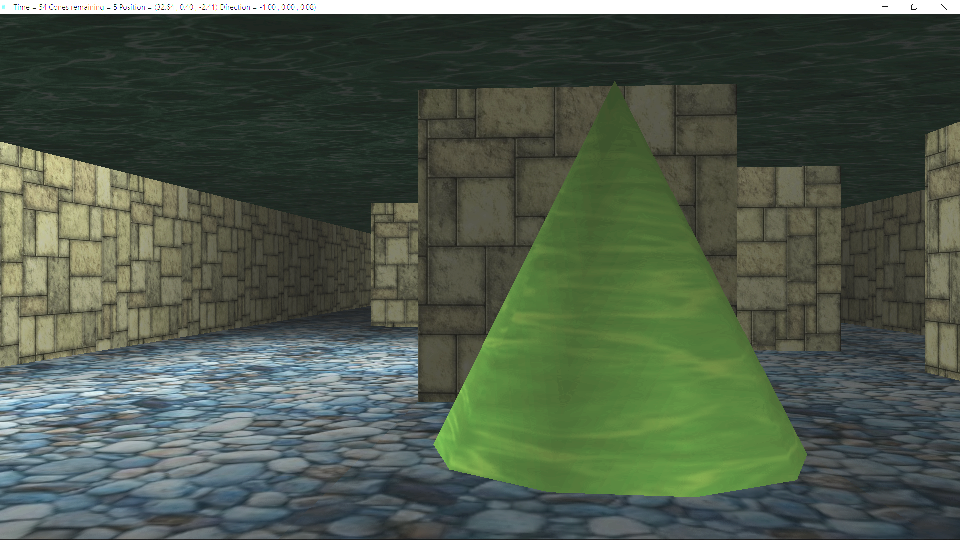
3D game
An example 3D game capturing cones in a maze that comes with the LitDev extension download (3D-samples/LD3DMazeGame.sb).
Mesh import
An example mesh import with a skydome that comes with the LitDev extension download (3D-samples/LD3DViewImport.sb).