Building a teamed virtual switch for Hyper-V from SCVMM
Hi!
A common question today is how to setup your cluster blades with (10GB) Ethernet connections. How do I configure that correctly with the following requirements:
- A LBFO (Load Balanced FailOver) Team of the available physical Connections.
- Several Networks which are controlled by QoS to not use up the entire channel.
Management Network
Cluster Network
iSCSI Network
Live Migration Network
(Optional) multiple isolated virtual networks
Let’s see how this can be build using SCVMM 2012 R2.
I start with 2 Nodes. Each has 3 Ethernet interfaces. Ethernet1 is already used by a virtual switch (NodeSwitch). The Switch used Ethernet1 as a team with one NIC.
A virtual NIC vEthernet(Management) is exposed to give the Host Network connectivity
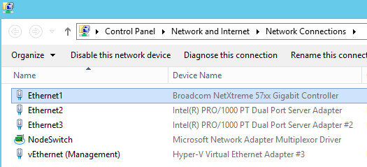
This Setup makes it easier to build the desired switch with the 2 remaining NICs, as I will always have connectivity during the creation of the new switch. Later, I can easily destroy the NodeSwitch and add Ethernet1 to the newly build Switch as 3rd NIC.
Let’s start building:
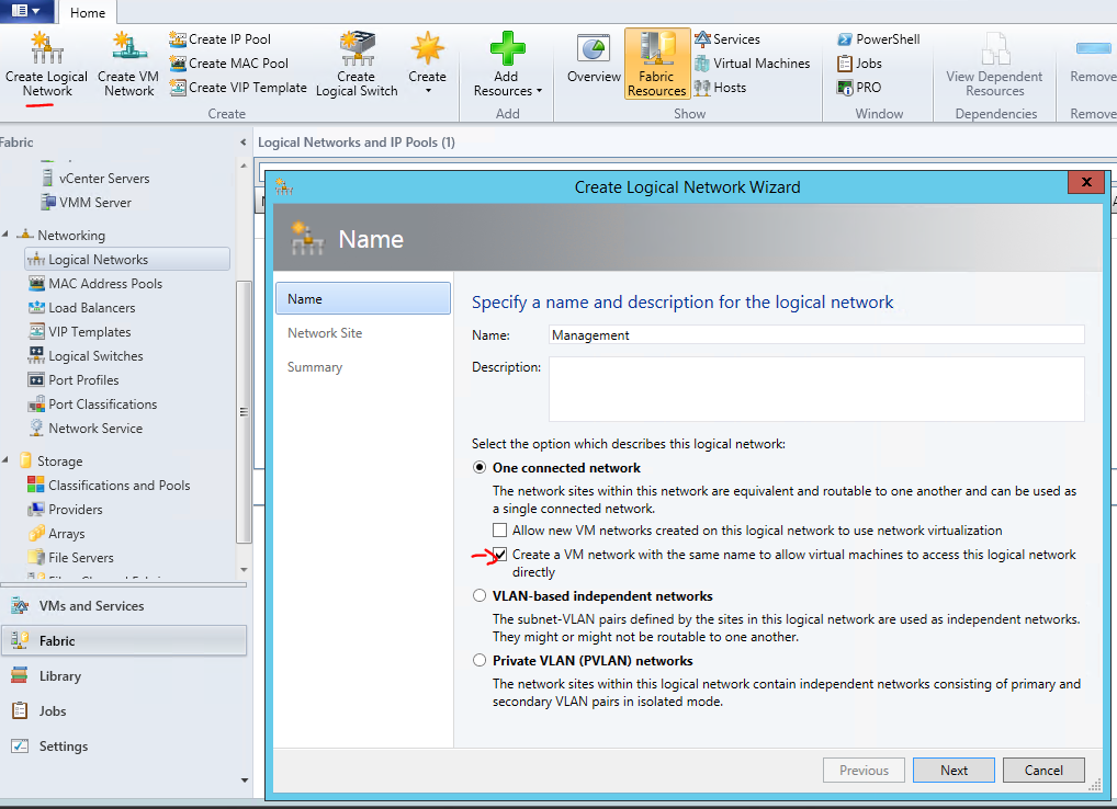
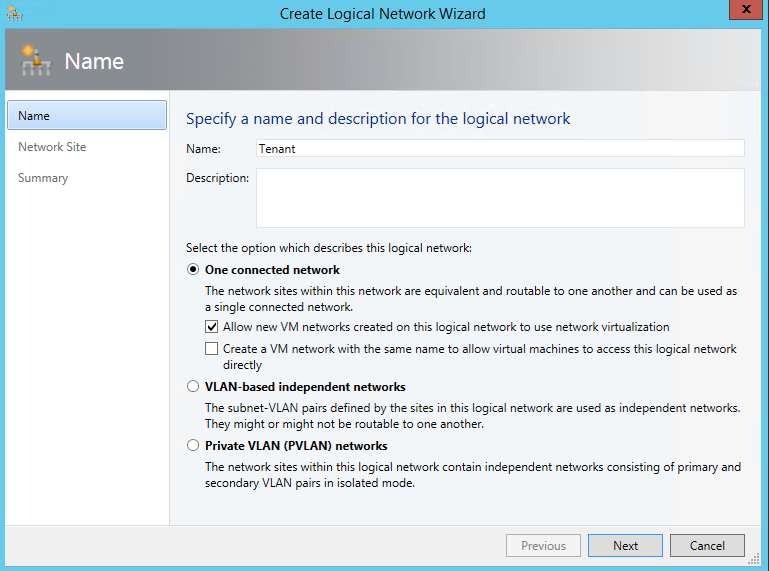
1. Define the Logical Networks the new Switch should connect to.
The Wizard allows you to already create an identical VM Network right here. As you always need a VM Network mapped to one logical Network let’s use this.
First creating the “Management” Logical Network:
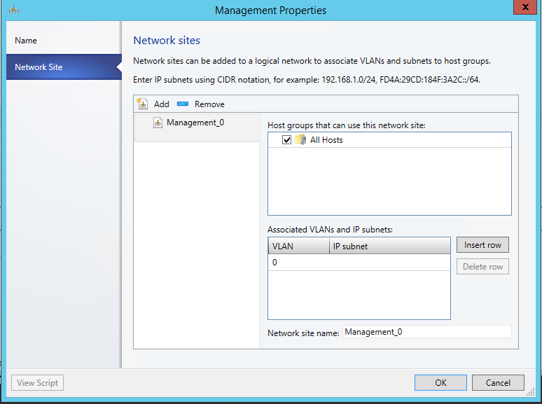
Add a Network site for this Logical Network. Here is the IP Address range for my management purposes. It matches my DHCP Scope, so I do not specify that again here.
Do the same steps to create the other Networks. To allow separation and QoS of those connections you have to work with own subnets on top of the existing network.
I use:
Tenant (172.31.10/24), Cluster (172.31.2.0/24), iSCSI (192.168.1.0/24) , Live Migration (172.31.3.0/24)
When adding the Network Sites for those specify the IP Subnet.
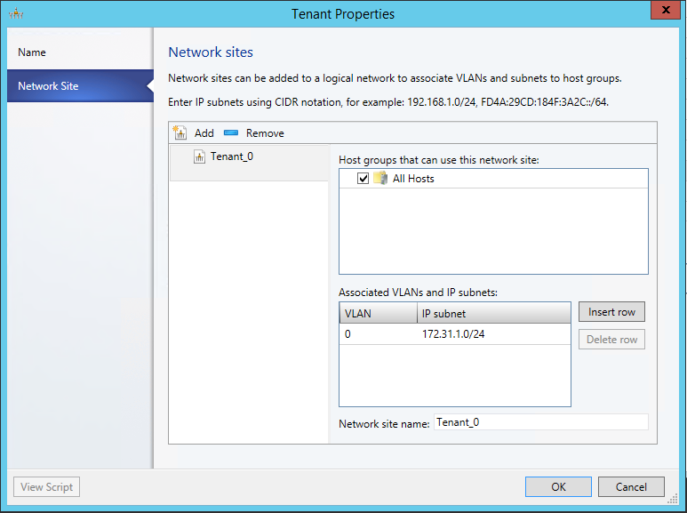
For the Tenant Network, specify to use Network virtualization and don’t create the VM network yet.
As it uses Network virtualization we can connect several isolated VM Networks later (Red and Blue)
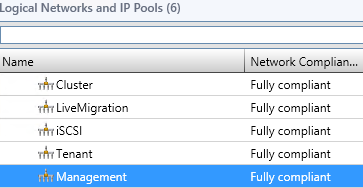
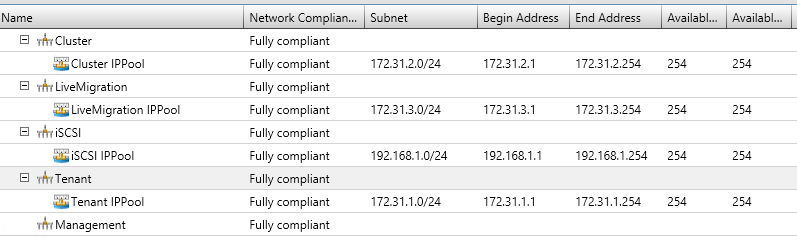
That results in the following logical Networks
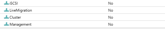
And corresponding VM Networks:
Back on logical Networks, create IP Pools on each Network so that VMM can give that out statically later. (I just accepted the defaults, after giving it a corresponding name…)
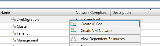
Just as Management Network is using DHCP in my case, no need for an IP Pool.
Now as we have created these Networks, we can start building the Switch Template using those.
(You can later create new Networks, and associate it with the Template, if you have to.)
2. Define the Uplink Port Profile for your new switch.
We need to specify which networks are reachable by the switch.
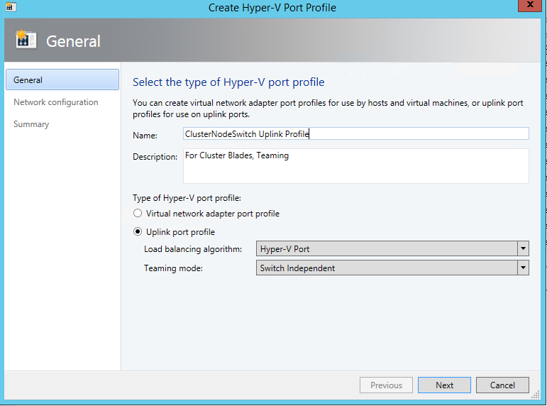
As I used the switch for VM’s mainly, I use Hyper-V Port balancing.
Next, add all Network Sites this switch will be connected to, and enable Network virtualization too
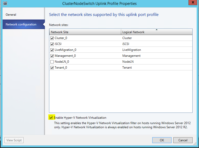
NodeLN_0 belongs to my other Switch. So not connecting it here.
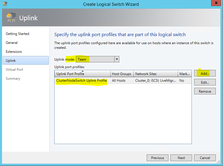
3. Create new Virtual Switch Template (Name ClusterNodeSwitch)
Here the important part is to select Uplink mode, and Add the previously created Uplink Port Profile
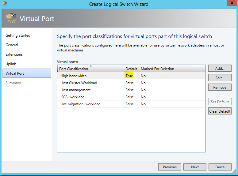
Next, we need to specify which Virtual Ports with which qualification should be available when later placing the switch. You could basically include every type here, and pic later the ones you need.
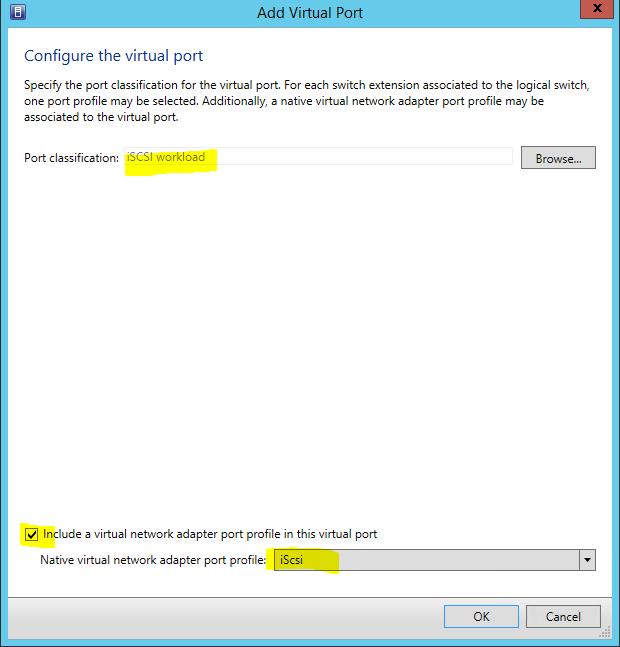
I did this for the possible networks I created previously. The Default helps to have the field prepopulated later when I assign VM Networks to VMs.
4. Finally, placing the switch on the nodes.
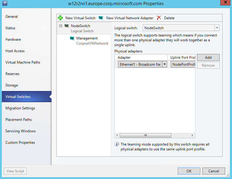
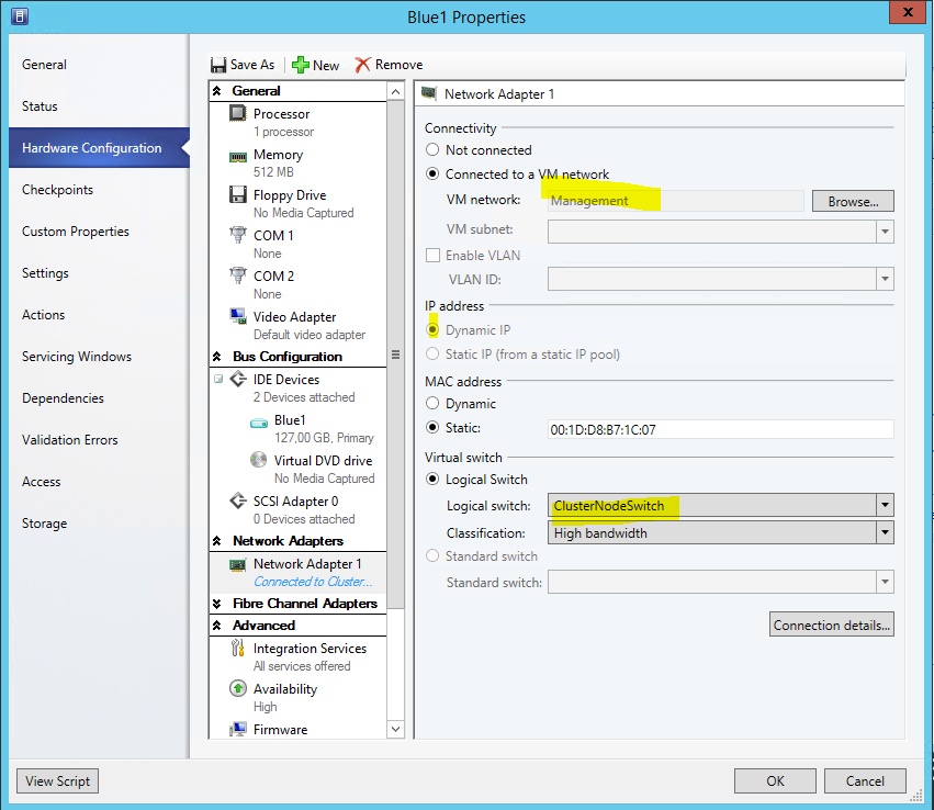
Here’s one of my hosts properties before placing the switch: (as this was pre-existing, to how the differences later. There is no need to have this)
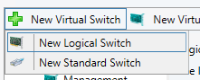
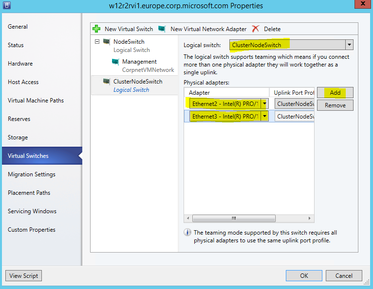
Start adding a New Logical Switch
Select the right Switch Template, and adding the physical NICs
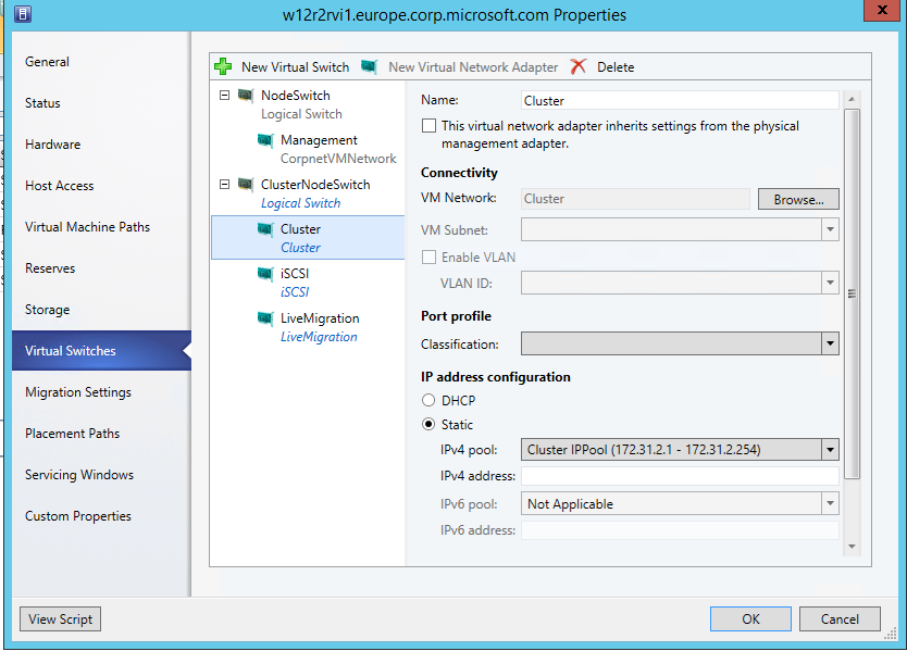
Now, create the Virtual Network Adapters the Host should have available for it's use. Otherwise it would have no connectivity.

I chose not to inherit the settings, as I have a already existing management connection. This is required if you have no other connection yet.
For all Networks I selected to pick a Static IP from the suggested pool
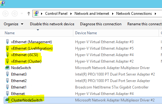
Do the same on the other nodes….
So in NCPA on one node this now shows as:
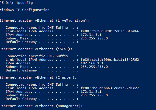
Ipconfig:
All those Networks also show up in Failover Cluster Manager. (I’ve given them the correct names based on the used IP already.
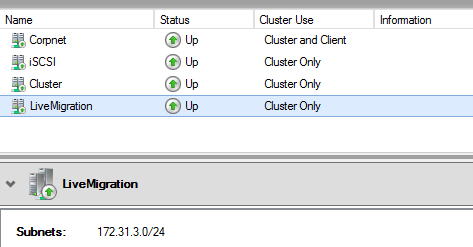
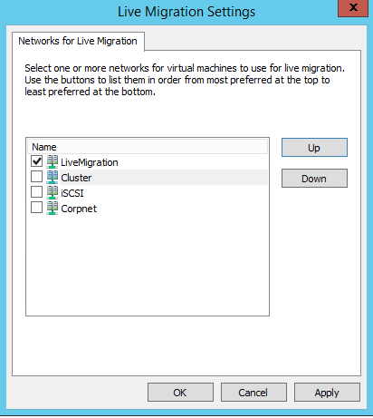
Now, select the correct Network for LiveMigration:
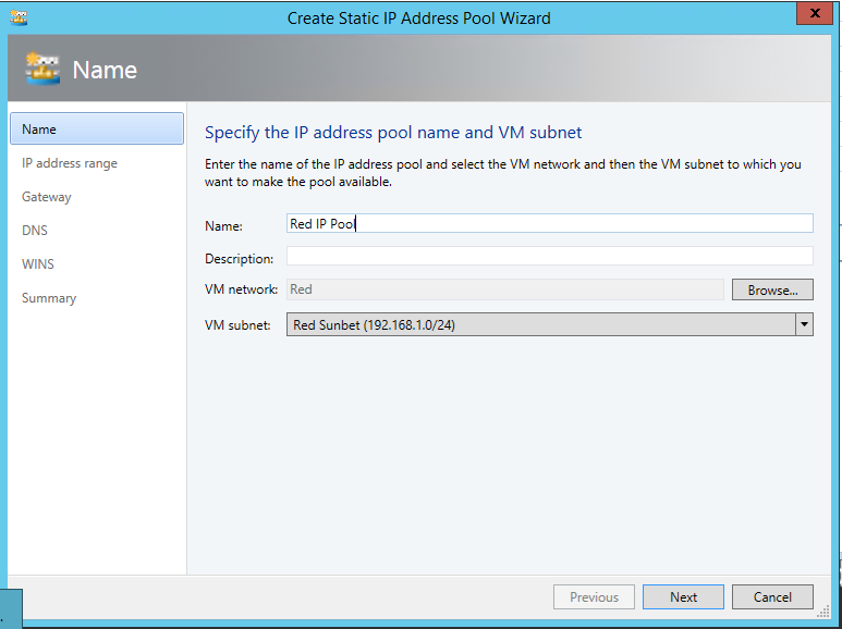
5. (Optional): Create Isolated BLUE and RED VM Networks
To run virtual networks with identical subnets, isolated, you create VM Networks that map to the Tenant Logical Network.
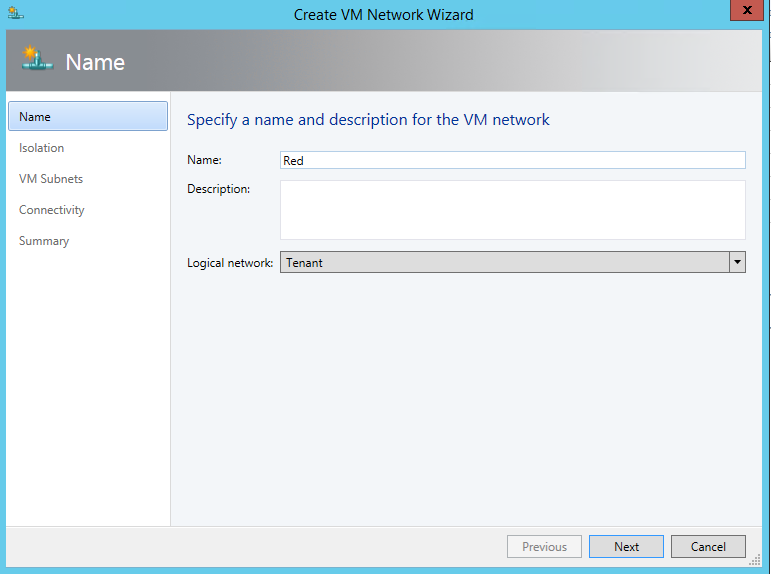
Give it a subnet that might seem to collide with your on premises or other VM Networks, but it’s isolated.
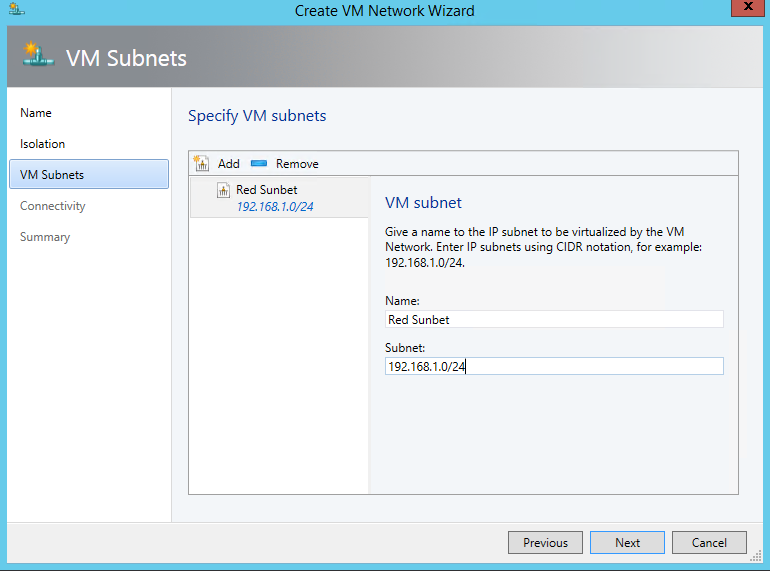
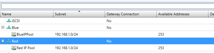
And we create an associated IP Pool, so that we can assign later IP addresses to the VM and they will receive them from a DHCP extension installed in every Hyper-V switch.
Doing the same for Blue, creates us two isolated VM networks.
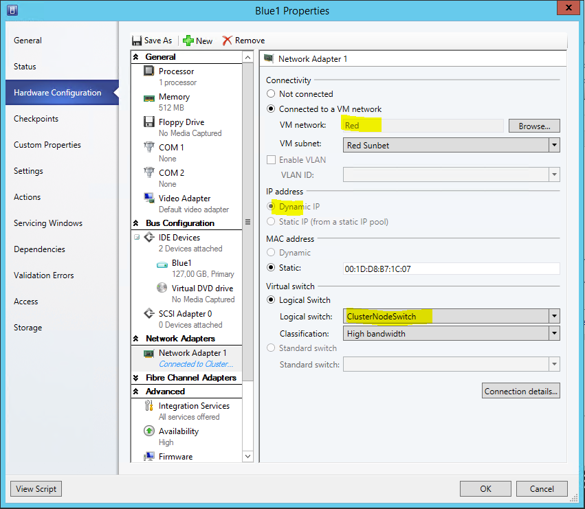
Now, to see that in action, I assign VMs to 3 different networks:
First, to my Management Network, it will get a DHCP address from there
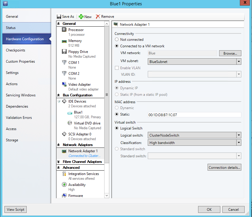
Second, to the Blue Network, DHCP on the Hyper-V Switch will give out IP address here
Lastly, to the Red Network, DHCP on the Hyper-V Switch will give out IP address here of the Red scope:
I hope that helps you better understand and use this cool feature. It turns out handy when you configure more then just 2 nodes.
Cheers
Robert