Building a Thermostat with the Microsoft .NET Micro Framework
Tony Pitman from Shatalmic is posting today as a guest contributor. He used the Emulator Temperature sample as a base to write this hardware guide for attaching a SPI temperature sensor to either a iMXS or a Tahoe dev board.
Building a Thermostat with the Microsoft .NET Micro Framework
By Tony Pitman
Introduction
During the summer of 2007 Microsoft released service pack 1 for the .NET Micro Framework. Soon after the release of the service pack Microsoft posted a few new samples. One of these samples is a thermostat based on an SPI temperature sensor from Analog Devices.
Sample Application
The sample uses the .NET Micro Framework emulator component architecture to simulate the actual hardware. This is one of the many really cool features of the .NET Micro Framework development environment and architecture. Being able to not only simulate hardware exactly the way it will work on the real silicon, but do so using C# and manage classes is something the embedded industry has not seen before.
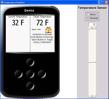
Figure 1
I spent some time looking at the sample emulator. I started to wonder how hard it would be to actually make the hardware for the temperature sensor, and hook it to one of the development boards that is available for the .NET Micro Framework.
Developer Boards
The .NET Micro Framework home page lists some companies that provide hardware to run the .NET Micro Framework. Look for the section on Developer Kits.
Since my company has already done some work with the Embedded Fusion development kit, I decided to try connecting the Analog Devices temperature sensor to the Embedded Fusion Tahoe board. You can also use the Freescale iMXS SideShow Development board for this project, but there are some small changes. I note these changes at the bottom of this article.
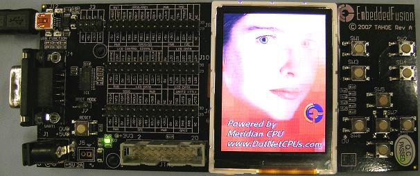
Figure 2
The Tools
The tools that you will need for this project are pretty standard. You will need a soldering iron, some solder, wire cutters and wire strippers. If you are really good with the wire cutters you can probably do without the wire strippers. I also like to have a pair of tweezers to place the small parts onto the breading board.
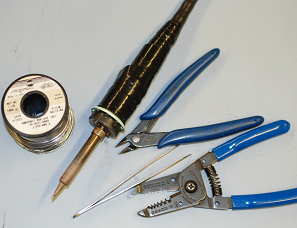
Figure 3
The Parts
There are not many parts that you will need to connect the temperature sensor to the Tahoe board. You will need the sensor chip, a breading board, a header connector and some wire.
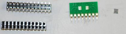
Figure 4
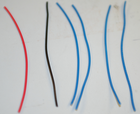
Figure 5
I like to use the standard red and black for power and ground and blue for signal lines.
Digi-Key carries the parts that you will need. Here is a list of the part numbers with the last known web page for ordering them from Digi-Key:
SPI Temperature Sensor: AD7314ARMZ-ND
Breading Board: 33108CA-ND
Header Connector: S5682-ND
Total cost to me with USPS shipping came to about $13. The items came in the mail in about 4 days.
Now that we have all the parts and tools that we need, let’s get started...
Soldering the Chip
The first thing I did was solder the temperature sensor onto the breading board. The pins are kind of small, but with a decent soldering iron shouldn’t be too difficult. I am mainly a software guy, so my solder jobs are not the best. If I can do it I am sure most people can.
If you prepare the pad on the breading board with a little extra solder it helps. Just don’t put too much or you will end up having bridges across the pins. A soldering jig would probably make things much easier, but since I don’t have one I like to use tweezers to hold the part in place while I solder the first pin.
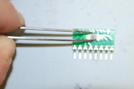
Figure 6
If you have added just a little extra solder to the breading board before placing the part, you should be able to hold the part in place with the tweezers and heat one of the corner pads just enough to hold the part in place. Once you have done that it is pretty easy to heat each of the other pins carefully to complete the job.
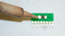
Figure 7
Once you have completed soldering the pins carefully check to make sure you don’t have any solder bridges between the pins.
Attaching the Wires
Now we can move on to attaching the wires. The pin out for the AD7314 temperature sensor chip is as follows:
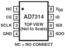
Figure 8
This puts pin 1 to the far left of the breading board when the pins of the breading board are pointing down.
Since the AD7314 uses the SPI bus to communicate, we will be connecting the pins to the SPI port of the Tahoe board. Using SPI requires a chip enable pin. This is usually a standard GPIO pin on the host. For our project we will use GPIO pin 5. This pin is labeled PA7 on the Tahoe board.
Besides connecting power to a 3.3 volt source, and ground to a ground pin, we just have to connect the SPI pins for SCLK (serial clock), SDI (serial data in) and SDO (serial data out). Serial data in and out on the AD7314 are from the perspective of the AD7314 chip.
I chose to solder the wires to the breading board first. As you can see in Figure 9; I soldered the blue wires to the signal pins, and the red and black wires to power and ground respectively.
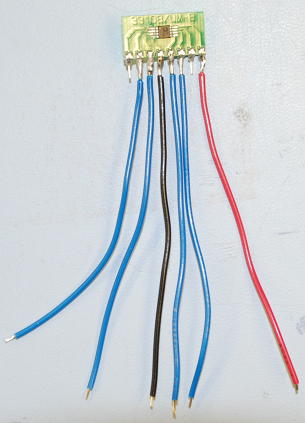
Figure 9
Starting from pin 1 (the left most pin) you can see that the wires match the pin out in Figure 8.
The Header Connector
At this point I have to note that the types of headers I got were not the best. At the time I placed my order the only type that I could find from Digi-Key were surface mount headers. This means the pins that I solder to are horizontal instead of vertical.
This made solder to them a little more difficult, but not impossible. I would recommend getting some headers with the pins coming vertically out the bottom of the headers. Either type will work fine. You may just find that the vertical pins are easier to solder to.
You could also choose to purchase a single row type header connector. I chose to get the 2 row connectors so that I could use them to also connect to the Freescale developer board which requires 2 rows to hit all the pins that are used.
Now we move on to soldering the wires to the header connector. The header connector on the Tahoe board that contains the SPI bus is J6. Embedded Fusion has done a great job of labeling the connectors and what functions each of the pins performs.
If you look at J6 on the Tahoe board you can see that the SPI bus pins are all grouped together in a section conveniently labeled SPI as shown in Figure 10. This contains what Embedded Fusion has labeled MISO (master in, slave out), MOSI (master out, slave in) and SCLK (serial clock). These labels are a little different than what the AD7314 called them, but it is easy to match them up.
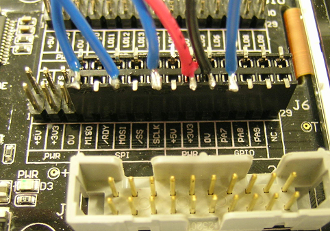
Figure 10
Since the Tahoe board is the master we can match them by connecting the master in, slave out (MISO) pin on the Tahoe board to the slave serial out (SDO) pin. MOSI on the Tahoe goes to SDI on the AD7314. SCLK is easy as it goes from SCLK on the Tahoe to SCLK on the AD7314.
Embedded Fusion made connecting devices to their Tahoe board extra easy by placing 5v, 3.3v and ground (what they call 0.0v) pins all over the place on each header. You can see these pins just to the right of the SPI section in a section labeled PWR.
We connect our red wire (pin 8 on the breading board) to the +3.3v pin on the Tahoe and our black wire (pin 4 on the breading board) to the 0.0v (GND) pin on the Tahoe.
Now the only pin left to connect is the GPIO for chip enable. This is pin 2 on the breading board and as mentioned above I have connected it to GPIO pin 5. This is a little more to the right on the same row of pins on the Tahoe board and is labeled PA7.
If you are wondering what the PA7 stands for it is actually Port A, pin 7 on the Freescale iMXS processor chip that the Tahoe board uses as its main processor. Internally Embedded Fusion has mapped GPIO pin 5 to Port A, pin 7 on the processor.
That is all there is to hooking up the AD7314 SPI temperature sensor to the Embedded Fusion Tahoe board. Now we can move on to the software changes.
The Sample Application
When Microsoft created the .NET Micro Framework they must have at least a few people with embedded experience on the team. I say this because they really did think of many of the things that embedded developers would have to deal with. One of those things is being able to simulate hardware without having to actually build the hardware.
The .NET Micro Framework has an emulator system. This article is not meant to be an explanation of the emulator, but I did want to point out one very important feature. Any developer can write what is called an emulator component.
Emulator components are software that acts like hardware. You can create devices that connect up to the emulator system in such a way that the managed drivers that you write can’t tell the difference between talking to an emulated component or the real thing.
The temperature sensor sample application has such an emulated component. The source code is all included and I recommend taking a look at it. The emulated AD7314 component “connects” to the emulator’s SPI bus and responds in exactly the same way that the real AD7314 responds. This allows the developer to write their AD7314 managed driver using the emulator and know that the same device driver will work with the real AD7314 hardware.
Differences Between Platforms
Even if we were not dealing with going from running our application on the emulator versus the hardware each hardware platform usually requires its own libraries to access it.
The Embedded Fusion Tahoe board has a set of libraries that ship with the board. Not only do these libraries give access to the specific hardware on the Tahoe, but also add a lot of great functionality.
Embedded Fusion Tahoe SDK
If you have not done so already, you will need to install the Embedded Fusion Tahoe SDK that came with your Tahoe board. I always recommend checking the Embedded Fusion web site to download any new versions of the SDK.
Copy the Project
At this point I would recommend that the reader copy the TemperatureSensor sample application to a new folder. I called my new folder TemperatureSensor – Hardware. Make sure that you don’t have the solution open in Visual Studio when you copy it. Once you have copied the project, open it in Visual Studio.
Embedded Fusion Tahoe References
The first modification that we will have to make to the sample application is to add the references to the Embedded Fusion Tahoe libraries.
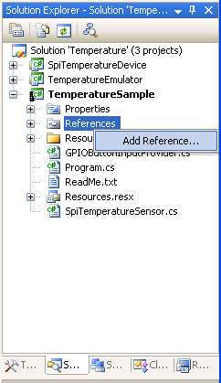
Figure 11
Find the Solution Explorer in Visual Studio. One of the items under the project is labeled References. Right click on References and choose Add New Reference. A dialog appears that shows the available libraries that you can add as shown in Figure 12.
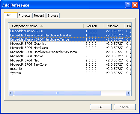
Figure 12
If you properly installed the Embedded Fusion Tahoe SDK you will see 3 components in the list that start with EmbeddedFusion. Highlight all 3 of them and click the OK button. You will now be able to use and reference EmbeddedFusion specific functionality in your project.
There are 2 places where we need to use Tahoe specific functionality. The first place is in the button implementation. If you come from a PC programming background, then you are probably used to having input devices available in a generic way. When you enter the truly embedded world you will often find that input comes in the form of interrupts and GPIO pins. This is going on under the hood on a PC, but the OS deals with it for you.
The .NET Micro Framework allows the developer the flexibility to go all the way to the hardware without much fuss. There are a couple of helper methods, however, that can make button input easier and provide a more “OS” like feel.
Button Input
Open the GPIOButtonInputProvider.cs source file by double clicking on it. This class is actually provided any time you create a new Window Application for the .NET Micro Framework using the New Project Wizard in Visual Studio.
In order to reference the correct GPIO pins on the Tahoe board we have to add a using statement to the top of the GPIOButtonInputProvider.cs file. You can see that I did this in Figure 13.
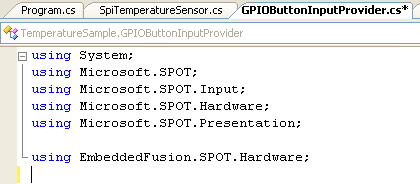
Figure 13
Next we need to change the button pin mappings that point to the emulator button pins to the Tahoe board pins for the same buttons. Figure 14 shows the lines that are in the emulator sample and Figure 15 shows the changed lines. Notice that the only change is the pins that the buttons are mapped to. The pins for the emulator are generic hardware pins and the pins on the Tahoe are specific to the Tahoe board.
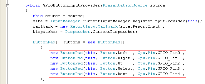
Figure 14
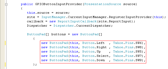
Figure 15
SPI Chip Select
The only other thing that is different between the emulator and the actual hardware device is which pin to use for the SPI chip select. All of the code for the managed SPI driver is contained in the SpiTemperatureSensor.cs file source file. Open that file now.
At the top of the file you will see using statements similar to the button source file. Again we need to add the reference to the Embedded Fusion libraries. You can see that I added them in Figure 16.
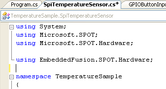
Figure 16
Now we are ready to make the change to the chip select pin that will be used to talk to the AD7314 over the SPI bus. In Figure 17 you can see the original code and in Figure 18 you can see that simple change that I made.
class SpiTemperatureSensor
{
/// <summary>
/// Keep this private member around as the SPI object
/// </summary>
private SPI _spi;
/// <summary>
/// Standard public constructor
/// </summary>
public SpiTemperatureSensor()
{
// Get a new SPI object that is connected to the temperature sensor
_spi = newSPI(newSPI.Configuration((Cpu.Pin)5, true, 0, 0, false, false, 4000, SPI.SPI_module .SPI1));
}
Figure 17
class SpiTemperatureSensor
{
/// <summary>
/// Keep this private member around as the SPI object
/// </summary>
private SPI _spi;
/// <summary>
/// Standard public constructor
/// </summary>
public SpiTemperatureSensor()
{
// Get a new SPI object that is connected to the temperature sensor
_spi = newSPI(newSPI.Configuration(Meridian.Pins.GPIO13, true, 0, 0, false, false, 4000, SPI.SPI_module .SPI1));
}
Figure 18
All of the rest of the parameters and functionality of communicating with the SPI AD7314 temperature sensor are exactly the same. In fact, it would even be possible and easy to change the emulator component to exactly match the settings that we just changed, so that you could simulate the exact hardware that you are running on.
Building and Downloading
All we have left to do is to build and download the application to the Embedded Fusion Tahoe board. We will need to change the settings for the project in order to do this, so right click on the project in the solution explorer window and choose properties from the pop up menu as shown in Figure 19.
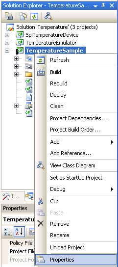
Figure 19
You should see a new dialog similar to the one in Figure 20. If you have already opened this dialog before for this project and clicked on one of the other tabs then the dialog will look a little different that what you see in Figure 20. No matter what tab the dialog is currently on, you should still see the tabs on the left side of the dialog. One of these tabs should be labeled Micro Framework.
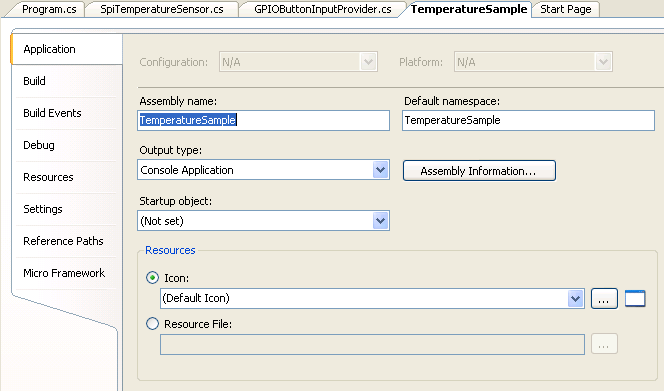
Figure 20
Select the Micro Framework tab and you should see the same window as shown in Figure 21.
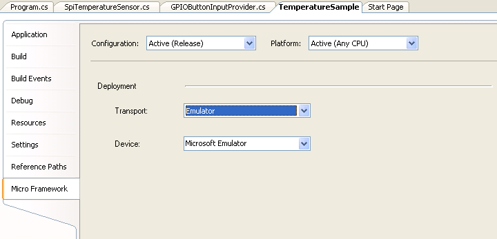
Figure 21
If you have built the Temperature Emulator project sample and already changed this sample device to point to it then the Device: drop down should already say Temperature Emulator. This doesn’t really matter to what we are doing, however.
Make sure that you have connected the Embedded Fusion Tahoe board to your PC and installed and configured all of the drivers successfully. If you have then connect the Tahoe board at this time if it is not already connected.
Once you have connected the Tahoe board you can change the Transport selection to USB. When you do this the Device drop down should automatically populate with Meridian_xxxxxx where the x’s are replaced with an ID number that represents your Tahoe board. If you have trouble with the drivers or seeing the Tahoe board in the drop down list I am sure the great folks at Embedded Fusion will be happy to help you. You can visit their web site at https://www.embeddedfusion.com/.
If everything has gone according to plan and you have the Tahoe board listed under the Device drop down, we are ready to build and deploy the project to the Tahoe board.
You can simply click on the play button on the Visual Studio tool bar as shown in Figure 22.
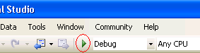
Figure 22
This will build the application and deploy it to the Tahoe board. Sometimes this can take many seconds, so be patient. If you get a build error, double check all of the changes that you made. Try disconnecting and reconnecting the Tahoe board if you get a deployment error. If you continue to have deployment problems you should contact Embedded Fusion for help.
If everything works you should see a display similar to Figure 23.
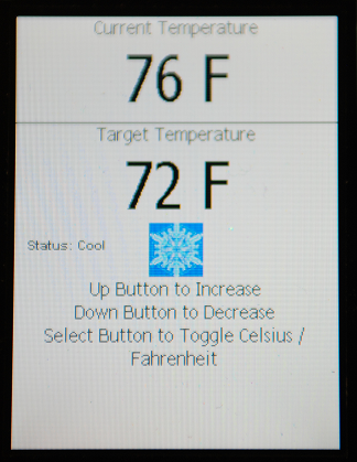
Figure 23
Freescale Developer Board
Hardware
There are a couple of differences between using the Tahoe board and the Freescale board. The button pins and GPIO chip select pins are different in the software and the pin connections to the board are different.
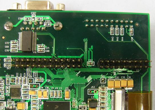
Figure 24
Figure 24 shows the top of the Freescale board. You can see a couple of the pins are labeled with SPI designations, but not all of the pins we will need to use are labeled. You will also notice there are several jumper wires soldered onto the board. The board I am using is version 1.3. If you have a newer board the jumpers may not be present and the pins may have changed. If that is the case I would recommend contacting Freescale to get the details of the changes.
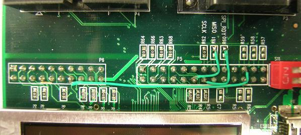
Figure 25
Figure 25 shows the pins on the back of the Freescale board. This is where you will have to actually connect the header connectors. As I mentioned above the breading board can be connected to the Embedded Fusion board by a single row header, but the Freescale board requires a 2 row header.
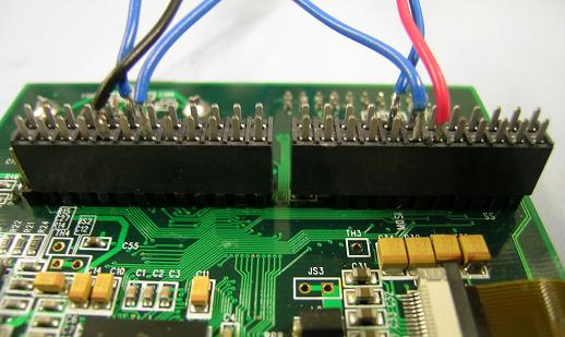
Figure 26
Using the same 2 row header connectors show above for the Embedded Fusion board you can connect the breading board to the Freescale board as shows in Figure 26.
As you look at the back of the Freescale board the same way as shown in Figure 26, notice that the connector on the left (labeled on the Freescale board as P5 on the front side) is plugged in so that it is all the way to the right of that connector. Also notice that the connector on the right (labeled on the Freescale board as P6 on the front side) is plugged in so that it is all the way to the left of that connector.
If you wanted to get smaller headers, you could do that as well. You really only need two 6 pin / 2 row header connectors. Using the larger connectors does make for a more robust connection and it is easer to line up on the correct pins as noted above.
Counting from the left, as shown in Figure 26, the connections are as follows (the following numbers are counted on the header and don't include the 2 left most pins that are not connected to the header):
Left Header Connector (P5):
| Furthest Row | ||||||
|
||||||
| Closest Row | ||||||
|
Right Header Connector (P6):
| Furthest Row | ||||||
|
||||||
| Closest Row | ||||||
|
Software
For the software you will change the assemblies that you include a reference to. Instead of the 3 EmbeddedFusion.SPOT references shown in Figure 12, you only include a single reference to Microsoft.SPOT.Hardware.FreescaleMXSDemo. The using lines shows in Figures 13 and 16 are also different. They should both be:
using Microsoft.SPOT.Hardware.FreescaleMXSDemo;
You will need to change the same lines of code detailed in Figures 15 and 18 above, but with different values. Here is a cross reference of the Tahoe pins versus Freescale pins:
For Figure 15:
| Tahoe Pin | Freescale Pin |
| Tahoe.Pins.SW6 | Pins.GPIO_PORT_B_16 |
| Tahoe.Pins.SW8 | Pins.GPIO_PORT_B_12 |
| Tahoe.Pins.SW5 | Pins.GPIO_PORT_B_11 |
| Tahoe.Pins.SW7 | Pins.GPIO_PORT_B_8 |
| Tahoe.Pins.SW9 | Pins.GPIO_PORT_B_10 |
For Figure 18:
| Tahoe Pin | Freescale Pin |
| Meridian.Pins.GPIO13 | Pins.GPIO_PORT_B_18 |
Conclusion
That’s really all there is to it. I hope you can see how easy it is to connect hardware to a .NET Micro Framework development board and write software for it. One thing to know about this sample and project is that with not a lot of extra effort this could be turned into a commercial product. You could easily create a high end thermostat device that could hook into a smart home network. What makes this even better is the fact that you could share .NET C# code between this application and an application running on a PC also written in Visual Studio.
The power and ease that Microsoft has brought to the embedded world is really cool. The possibilities are endless. Where do you want to go today? (I just had to say that).