Assembly of the Light Sensor Robot
The idea of this project is to build a simple robot that demonstrates control of motors using sensors. It is a light seeking robot that moves towards the brightest side. When the brightness on each side is the same, the robot moves forward. It can be steered with a flashlight. See the previous posts for parts and tools and for video of the working robot. Eduardo Velloso designed the robot, and I followed his tracks to build mine.

Assembly instructions
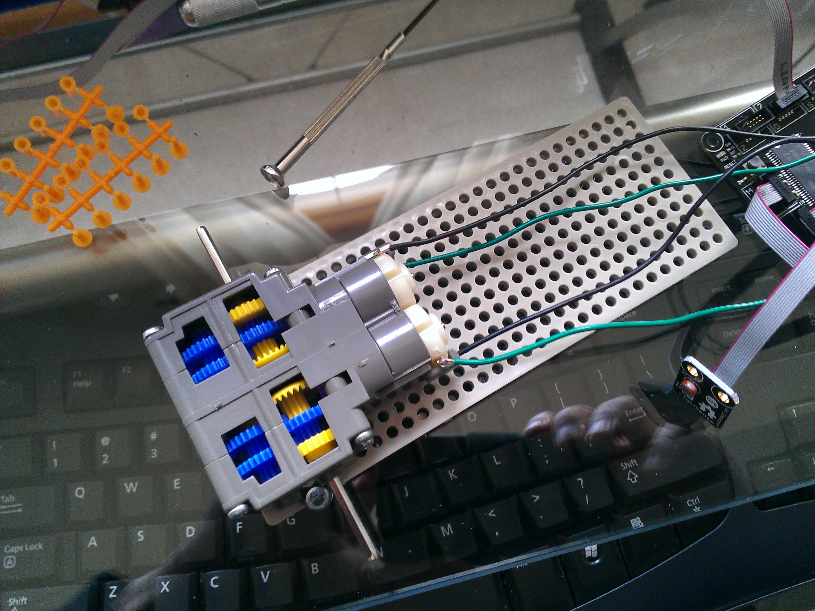
(1) Assemble the Gearbox
The instruction booklet that comes with the Tamiya gear box provides 4 different configurations for the gearbox. The first one, A, is the simplest, but it doesn't have enough torque to turn the wheels. So, use the fourth assembly, D. This is the most complex configuration, and it uses all gears.
Before installing the motors, solder four wires on the connectors. The polarity has to be the same on both connections to the motor driver so the wheels will turn the same direction.
(2) Mount the Gearbox on the base
In order to mount the gearbox on the base, we need to notch a bit on the sides of the plate using a side cutter. I mounted it on the third row from the top, using screws. In the first photo, below, the notch is right by my thumb.
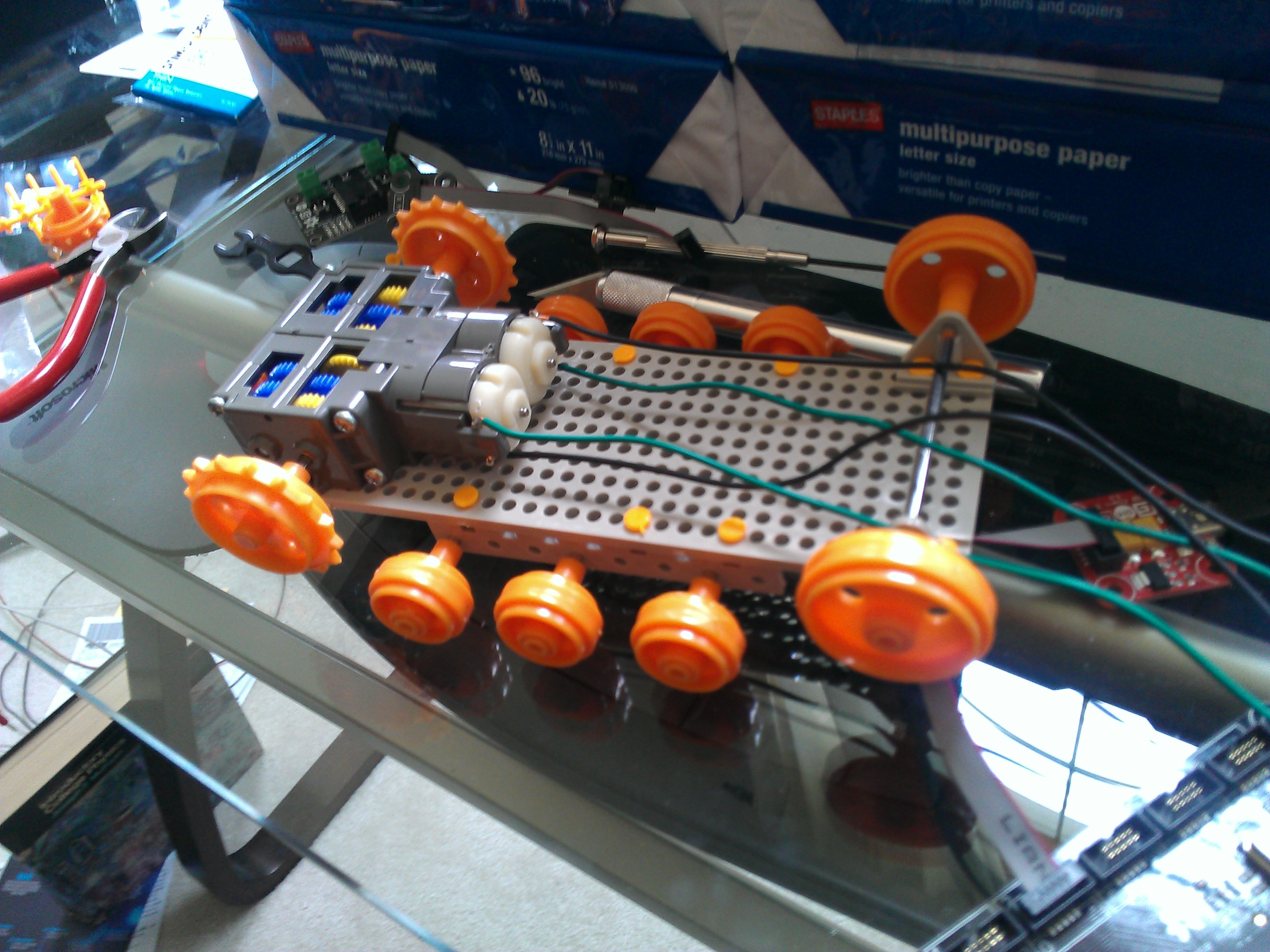
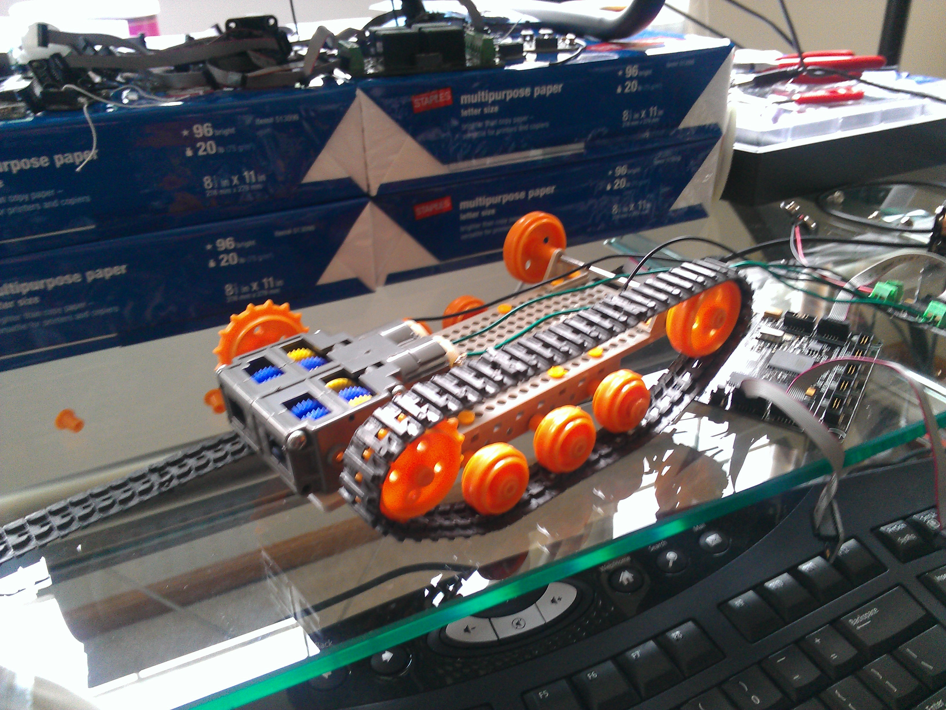
3) Mount the wheels
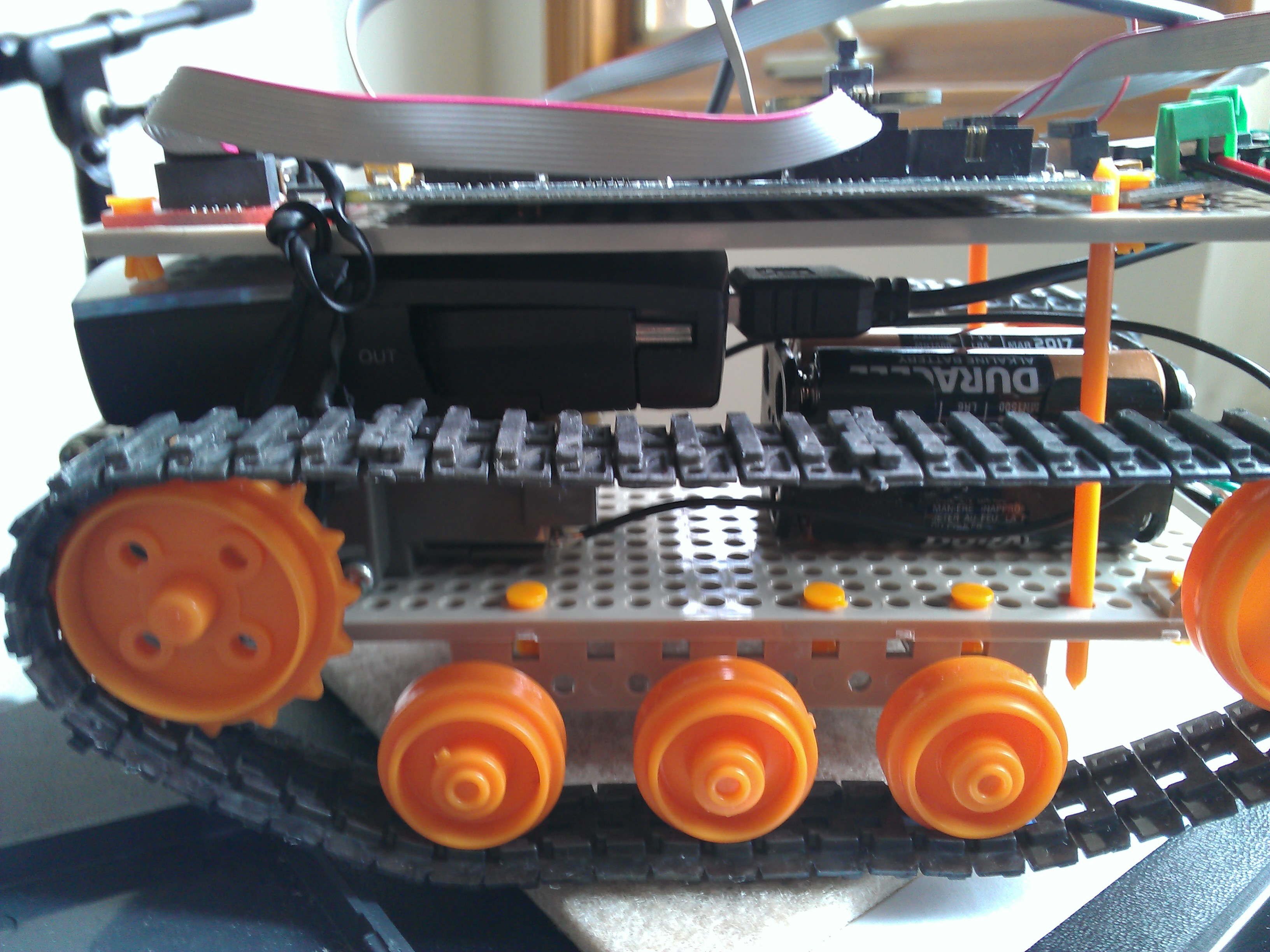
For the small wheels, mount an eight-hole angle bracket on each side of the bottom of the plate. Use round shafts, not hexagonal. For the large idler wheels on the top side use a single shaft mount. Mount the drive sprockets on the gearbox shafts, the small wheels on the bottom, and the large idler wheels on the top. Then, mount the tracks on the wheels. I was able to get the right length tracks using parts from the Tamiya kit.
(4) Mount the battery holder
There are various ways to mount the battery holder. You want to be able to remove it easily so you can disconnect the power to the motor driver and so you can change batteries. Eduardo attached it to the plate using velcro strips and installed a shaft mount in each side to stabilize it. He also attached another velcro strip on the top of the battery holder to attach it to the top plate. I used two pieces of plastic as supports (this was scrap plastic to which the wheels were attached in the Tamiya packaging). The vertical orange plastic supports are visible in the following photo.

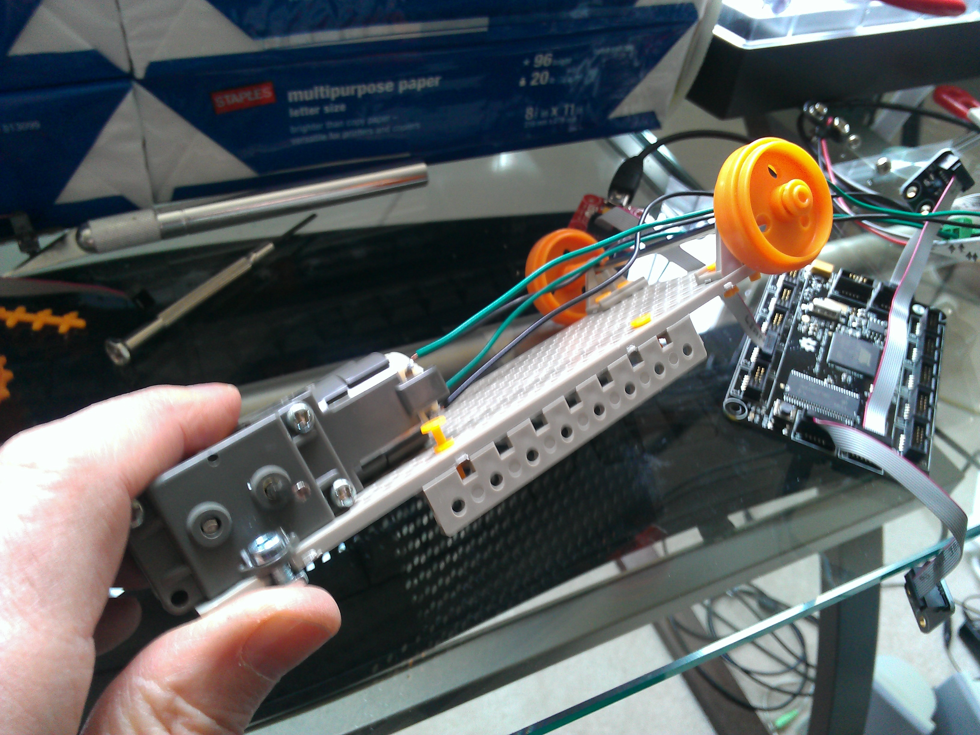
(5) Mount the board on the plate
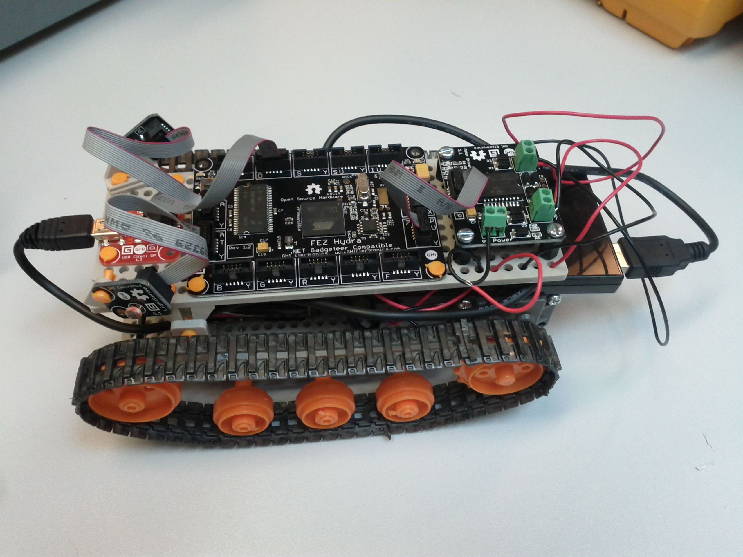
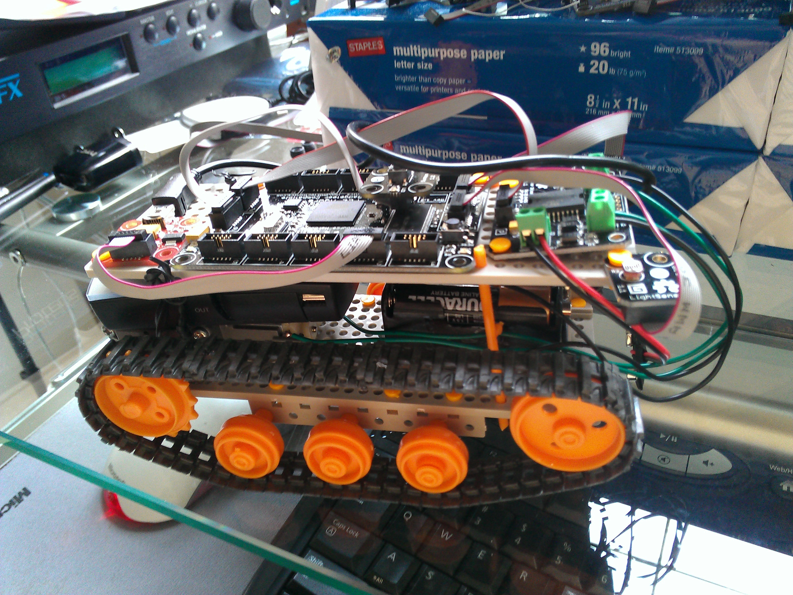
Mount the hardware on a second Tamiya plate, in the following order: power module, Hydra main board, motor driver, sensors, as shown in the following photo.
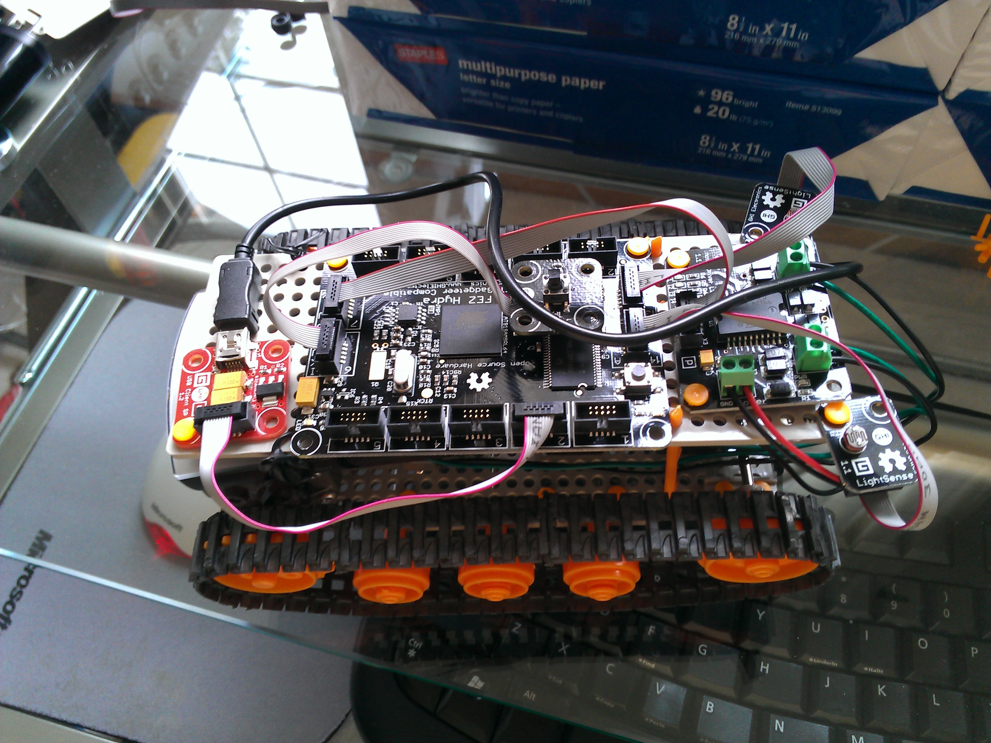
I used rivets to hold the sensors horizontally. Eduardo used shaft mounts to hold them vertically. You can shine a light from above on the sensors either way. In order to be able to adjust the angle of the sensors, mount the sensors or shaft mounts using one push rivet; this will attach the module or mount to the plate and allow it to rotate.
Eduardo's vertically mounted sensors are shown in the following photo:
My horizontally mounted sensors are shown in the following photo:

(6) Connect the modules and mainboard
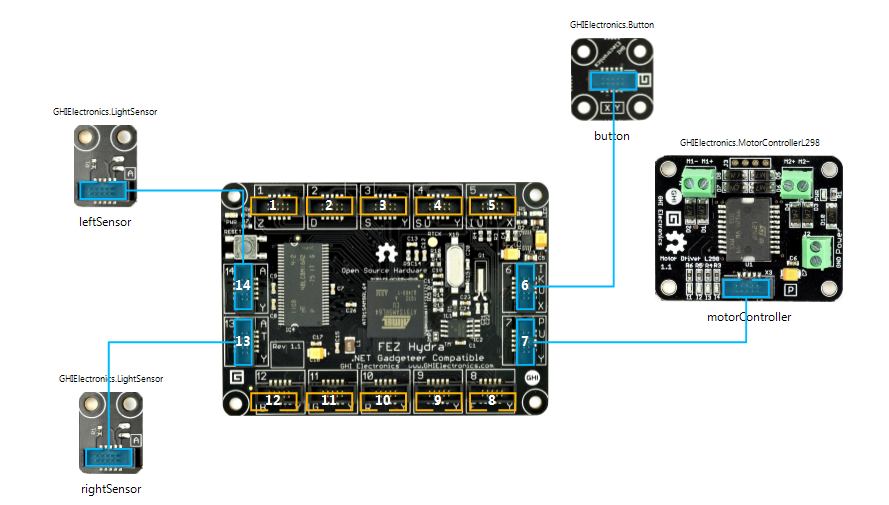
Use the ribbon cables, according to the Visual Studio Designer.
(7) Program the main board
The project code can be downloaded from: https://integral-data.com/robotsourcehydra.zip
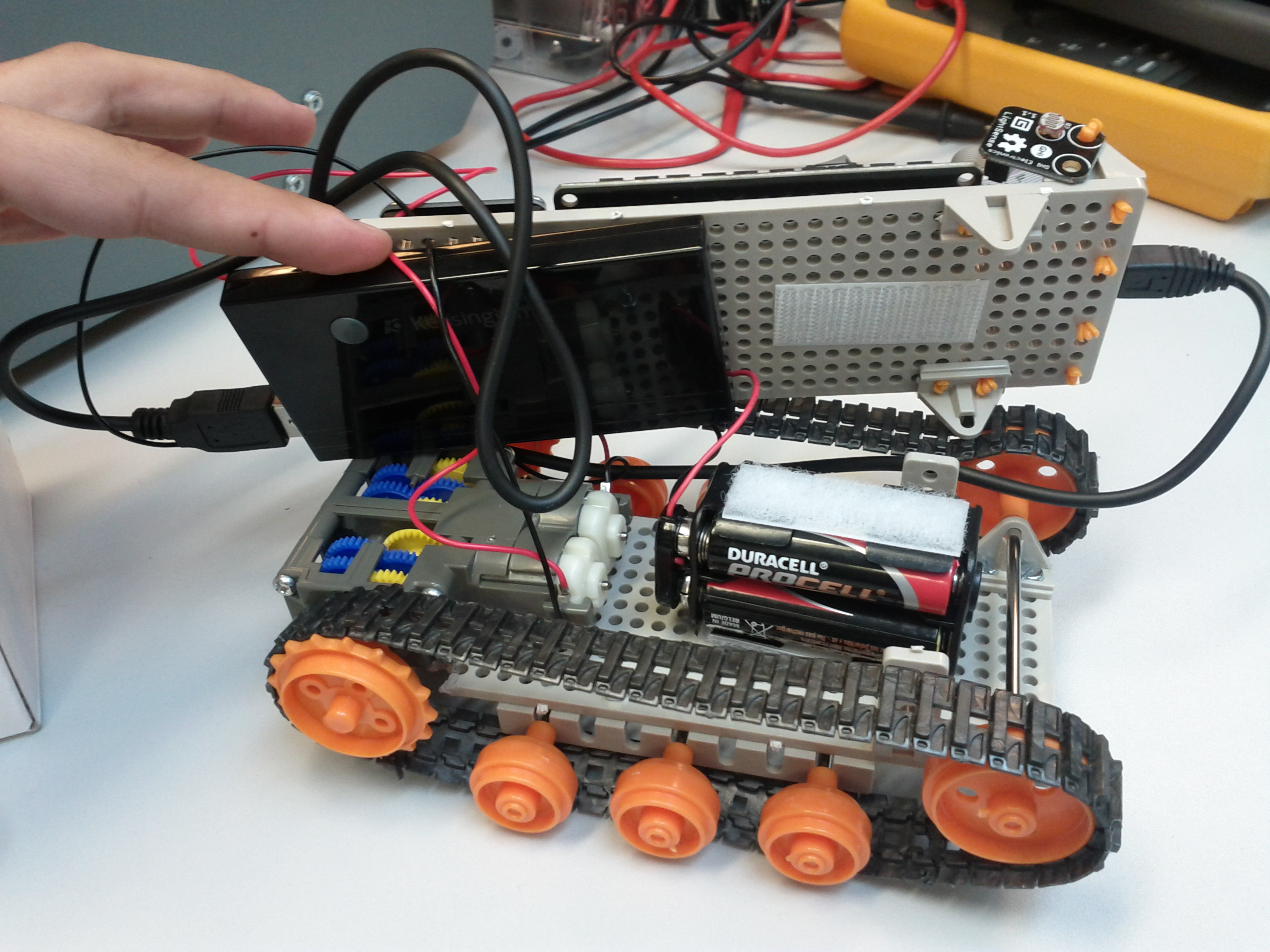
(8) Mount the battery
Eduardo used a velcro strip to the bottom of the plate where the hardware is mounted and also a velcro strip on the bottom of this plate to attach the battery holder and two more shaft mounts to help stabilize it. There are batteries to drive the motors and a lithium battery to power the .NET Gadgeteer mainboard. My lithium battery was a little thicker, so I set it on top of the gear box, sandwiched it between the two plates, and tied the plates with the connectors that come coiled around USB cables and other things.
Eduardos battery connections:
My battery connections:
NOTES:
- The Hydra board is wider than the plate, so it sticks out a bit (we only attached one side to the plate).
- Eduardo tried using two AA batteries to feed the motors, but the H-Bridge IC on this board needs at least 4.0V to start moving the motors. So, we used 4 batteries and set the motor maximum speed at 53% (around 3V). At this setting, the robot moves a bit slowly. It shouldn't be a problem to increase this voltage a bit.