New book: Programming with the Kinect for Windows Software Development Kit
 We’re happy to announce that Programming with the Kinect for Windows Software Development Kit (ISBN 9780735666818) is now available for purchase! In this book, David Catuhe, a developer evangelist for Microsoft, provides valuable guidance on how to create applications with Kinect for Windows. Learn about Kinect sensor technology, how the Kinect for Windows SDK works, how to integrate Kinect into your apps, how to develop a postures and gestures recognition system, how to use Kinect as a new input mechanism, and how to create an augmented reality app.
You can purchase the book here, here, or here.
In today’s post, please enjoy an excerpt from Chapter 3, “Displaying Kinect data.” If you would like to read an excerpt from the book’s Introduction, please see this previous post.
Chapter 3
Displaying Kinect data
Because there is no physical interaction between the user and the Kinect sensor, you must be sure that the sensor is set up correctly. The most efficient way to accomplish this is to provide a visual feedback of what the sensor receives. Do not forget to add an option in your applications that lets users see this feedback because many will not yet be familiar with the Kinect interface. Even to allow users to monitor the audio, you must provide a visual control of the audio source and the audio level.
In this chapter you will learn how to display the different Kinect streams. You will also write a tool to display skeletons and to locate audio sources.
All the code you produce will target Windows Presentation Foundation (WPF) 4.0 as the default developing environment. The tools will then use all the drawing features of the framework to concentrate only on Kinect-related code.
The color display manager
As you saw in Chapter 2, “Who’s there?,” Kinect is able to produce a 32-bit RGB color stream. You will now develop a small class (ColorStreamManager) that will be in charge of returning a WriteableBitmap filled with each frame data.
This WriteableBitmap will be displayed by a standard WPF image control called kinectDisplay:

This control is bound to a property called Bitmap that will be exposed by your class.
Before writing this class, you must introduce the Notifier class that helps handle the INotifyProperty-Changed interface (used to signal updates to the user interface [UI]):
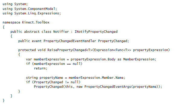
As you can see, this class uses an expression to detect the name of the property to signal. This is quite useful, because with this technique you don’t have to pass a string (which is hard to keep in sync with your code when, for example, you rename your properties) to define your property.
You are now ready to write the ColorStreamManager class:
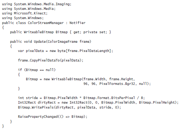
Using the frame object, you can get the size of the frame with PixelDataLength and use it to create a byte array to receive the content of the frame. The frame can then be used to copy its content to the buffer using CopyPixelDataTo.
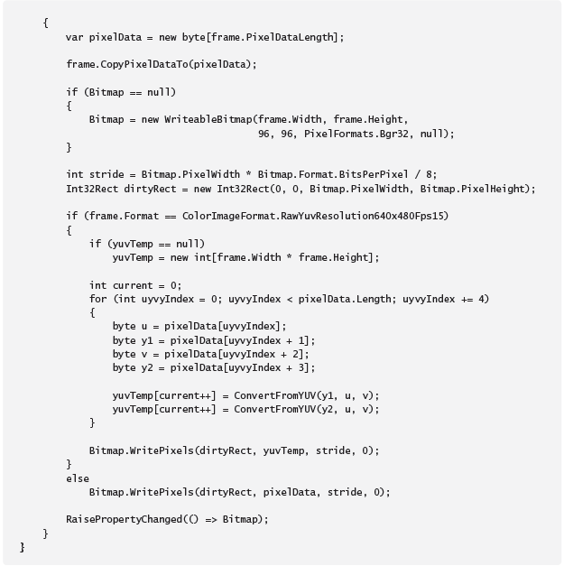
The class creates a WriteableBitmap on first call of Update. This bitmap is returned by the Bitmap property (used as binding source for the image control). Notice that the bitmap must be a BGR32 (Windows works with Blue/Green/Red picture) with 96 dots per inch (DPI) on the x and y axes.
The Update method simply copies the buffer to the WriteableBitmap on each frame using the Write-Pixels method of WriteableBitmap.
Finally, Update calls RaisePropertyChanged (from the Notifier class) on the Bitmap property to signal that the bitmap has been updated.
So after initializing the sensor, you can add this code in your application to use the ColorStreamManager class:
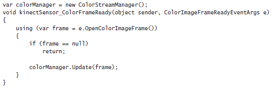
The final step is to bind the DataContext of the picture to the colorManager object (for instance, inside the load event of your MainWindow page):

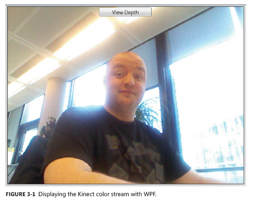
Now every time a frame is available, the ColorStreamManager bound to the image will raise the PropertyChanged event for its Bitmap property, and in response the image will be updated, as shown in Figure 3-1.
If you are planning to use the YUV format, there are two possibilities available: You can use the ColorImageFormat.YuvResolution640x480Fps15 format, which is already converted to RGB32, or you can decide to use the raw YUV format (ColorImageFormat.RawYuvResolution640x480Fps15), which is composed of 16 bits per pixel—and it is more effective.
To display this format, you must update your ColorStreamManager:
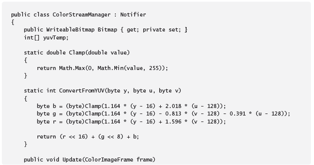
The ConvertFromYUV method is used to convert a (y, u, v) vector to an RGB integer. Because this operation can produce out-of-bounds results, you must use the Clamp method to obtain correct values.
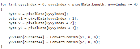
The important point to understand about this is how YUV values are stored in the stream. A YUV stream stores pixels with 32 bits for each two pixels, using the following structure: 8 bits for Y1, 8 bits for U, 8 bits for Y2, and 8 bits for V. The first pixel is composed from Y1UV and the second pixel is built with Y2UV.
Therefore, you need to run through all incoming YUV data to extract pixels:
Now the ColorStreamManager is able to process all kinds of stream format.
The depth display manager
The second stream you need to display is the depth stream. This stream is composed of 16 bits per pixel, and each pixel in the depth stream uses 13 bits (high order) for depth data and 3 bits (lower order) to identify a player.
A depth data value of 0 indicates that no depth data is available at that position because all the objects are either too close to the camera or too far away from it.
Comparable to the ColorStreamManager class, following is the code for the DepthStreamManager class:
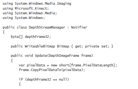
The main method here is ConvertDepthFrame, where the potential user ID and the depth value (expressed in millimeters) are extracted:
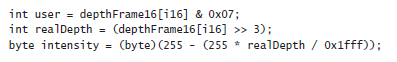
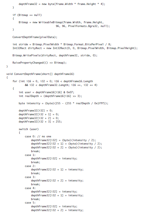
As mentioned in Chapter 2, you simply have to use some bitwise operations to get the information you need out of the pixel. The user index is on the three low-order bits, so a simple mask with 00000111 in binary form or 0x07 in hexadecimal form can extract the value. To get the depth value, you can remove the first three bits by offsetting the pixel to the right with the >> operator.
The intensity is computed by computing a ratio between the maximum depth value and the current depth value. The ratio is then used to get a value between 0 and 255 because color components are expressed using bytes.
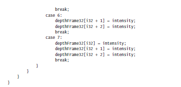
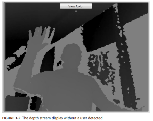
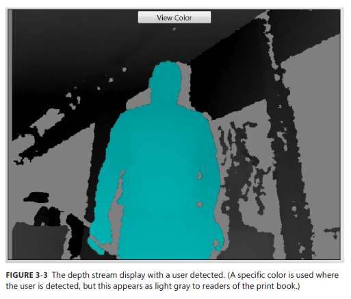
The following part of the method generates a grayscale pixel (with the intensity related to the depth), as shown in Figure 3-2. It uses a specific color if a user is detected, as shown in Figure 3-3. (The blue color shown in Figure 3-3 appears as gray to readers of the print book.)
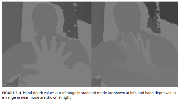
Of course, the near and standard modes are supported the same way by the DepthStreamManager. The only difference is that in near mode, the depth values are available from 40cm, whereas in standard mode, the depth values are only available from 80cm, as shown in Figure 3-4.
To connect your DepthStreamManager class with the kinectDisplay image control, use the following code inside your kinectSensor_DepthFrameReady event:
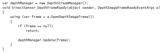
Then add this code in your initialization event:

The DepthStreamManager provides an excellent way to give users visual feedback, because they can detect when and where the Kinect sensor sees them by referring to the colors in the visual display.