The 'Meta-Model' and its relationship to the 'Factory Schema'
In the previous article, I talked about the power of the factory meta-model, and why you should have one in your factory. In this article, I want to describe how the meta-model is related to the factory schema, and how that can benefit both the factory author - defining her factory, and the factory user - operating his factory.
So what is this meta-model, and how is that related to the factory schema?
A software factory creates, or outputs a software 'Product' . The 'product of the factory' represents the solution domain of the problem the factory is trying to solve. The meta-model is a model of the factory product.
Defining the Product of your Factory
In order to achieve high levels of applicability, usability, productivity and efficiency, the factory can only address a finite set of the variability of the problem domain, and through careful application of constraints and relevant architectural design patterns - define an FPM to model the product line architecture that addresses this problem domain. The product model therefore, provides a relevant abstraction of the solution domain, which can then be used to define the factory viewpoints, assets, using automation.
The factory should be able to offer the most optimal technology/pattern to implement the product for the specified problem by baking-in the experience of the factory/tool builder gained from their experience of repeatedly solving these types of problems in the solution domain. This means, that if the factory changes its configuration, the factory may choose to use a different technology or pattern to solve the problem. (kind of the same principals a language compiler uses).
In order for the factory to adapt effectively to change in problem specifications, and adapt to changes in evolving solution requirements, the factory must maintain and persist a schema of the product that can be configured/re-configured at any time by the factory author to regenerate the assets for the factory. In turn, these assets re-generate a new solution efficiently and predictably for the factory user.
Starting with the 'Factory Product Model'
In order to do this, the factory runtime environment needs a 'logical model' of the product it creates - a 'meta-model', or more specifically a 'Factory Product Model' (FPM). (see previous article on the Factory Meta-Model)
This FPM, is used by the factory author to design the architecture of the software product the factory produces, in common terms to be understood by the factory user familiar with the problem domain.
We must try not to pollute this model with details about the physical implementation of the solution domain, instead choosing an appropriate abstraction of that. The factory user should not be assumed (by the factory author) to be an expert in solution implementation using the various specific technologies or patterns of the solution. Instead the FPM should describe the architecture of the product, in general solution domain concepts, easily understood by the factory user. Correctly done, this is one way to achieve useful abstraction using the factory.
The FPM describes the things the factory will configure and produce - the 'work product types' - and their relationship to the product of the factory. Furthermore, this FPM describes the hierarchical relationship of these work product types and how they are composed of other work product types, ultimately resulting in the product. In essence the FPM describes the logical composition of the factory product, devoid of the physical implementation and physical structure of the solution. More precisely, the FPM describes the 'Product Line Architecture' of the factory.
You can see below an example of a DSL designer that a factory author could use to define an FPM for their factory. This designer could equally be implemented in a hierarchical tree view type control.
This particular diagram shows the FPM for the EFx Factory as an example. In this case, the product created by the EFx Factory can be either an Application or Service or a System (composed of Applications and Services). Each Application or Service is itself a Module that can contain one or more Subsystems, and each type of Module (Application or Service) implements its own specialisation of a Subsystem.
From the toolbox in the designer below, you can define the product line architecture in very simple terms. The Product, a variant of the product (in the product line), Work products used to describe the logical components of the product, and relationships to represent inheritance and composition.
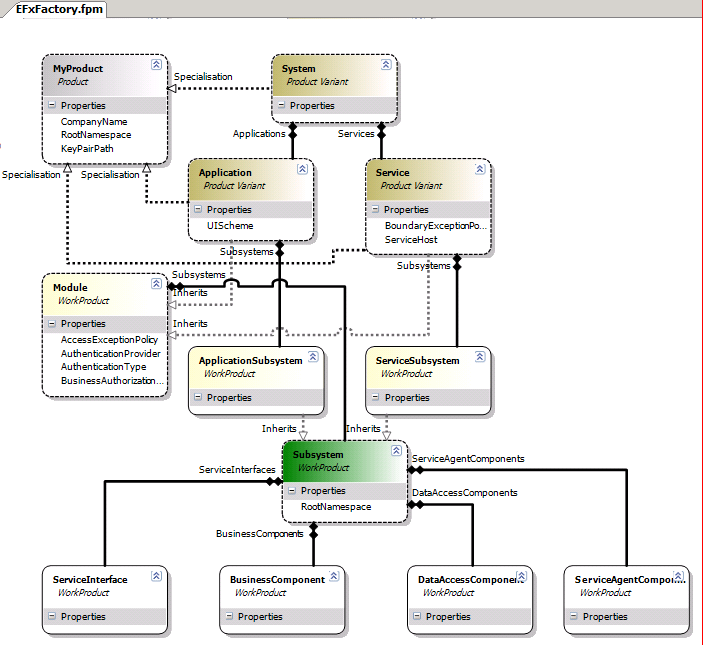
Figure 2. Illustrates the top level 'Factory Product Model' design for the EFx factory.
The entire logical model of all the factory (all work product types) are represented in this diagram but not fully described in this diagram. Each Work Product will be assigned an asset to build them. Some of the work product types are better described by other separate models (DSLs). The FPM designer has a shape called a 'Model Concept' (green shape) which denotes that a work product type is described in separate model (DSL), which may offer more detailed work product types (white shapes) and relationships for that specific domain. For clarity, we could call each of these model files a 'Work Product Type Model' (WPM) . These WPM models will ultimately be implemented as a single model file (DSLs) in the factory solution.
The other 'Work Product' shapes (yellow shapes) and 'Product Variant' shapes (brown shapes) in the diagram represent work product types that will ultimately realise themselves, physically, as either a solution, solution folders, projects or individual project files artefacts.
[A Work Product is physically realised as an Artefact. That may be a single artefact (e.g. source file). It may be artefacts in multiple files. Many parts of a single file, or multiple files (e.g. a partial class definition spread across one or many files). Maybe it's no physical artefact at all or maybe its configuration on a remote server somewhere.
Not all factories create source code.]
Therefore the entire FPM of the factory can be visualised in one file, and implemented across several model files: Product Model + Work Product Type Model(s).
[Note. This is not the view the factory user will see. Instead the factory user will be provided a 'view' over this FPM similar to the one
here , where they can create and configure the 'instances' of the work products of their instance of the factory. This is called the 'Product Explorer']
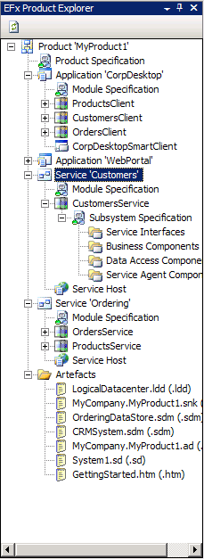
The Factory Schema
The FPM provides is powerful authoring experience for the factory author to define the product. A powerful user experience for the factory user creating an instance of the product.
The FPM (as a whole) provides a view across all the Work Products types, their Assets and mapping to the Artefacts from the factory schema. You can think of the FPM as a view of the factory you are building - a ViewPoint of the tool that lets you build your factory (that tool is the 'Factory-Factory' which you use to author your factory).
In fact, if ever there was a 'Factory-Factory-Factory' built (i.e. a factory that defined the schema for factory building :) ), that would contain a ViewPoint called a 'Factory Product Design'. This viewpoint would be defined as the following:
- The WorkProduct would be the 'Factory Product Model'
- The Asset would be the FPM Designer
- The Artefact would be the FPM Designer DSL file - MyFactoryProduct.fpm (in our case)
The FPM becomes a logical starting point for the factory author to begin to describe and their work products of the factory schema and their artefacts and assets needed to do that. It is simply one of the views of the factory schema. There will be others too that view the schema from different authoring aspects.
Generating the Factory Runtime
Since the FPM describes the work products and their assets, it can be used to generate runtime user tooling such as the views required to view the product (the 'Product Explorer') and launch the assets to create the WorkProducts. This tooling would then be used by the factory user to 'operate' the factory and manipulate the factory product. This tooling is then packaged and installed with the factory into the factory user's IDE. The factory user can then explore parts of FPM (and schema) visually in a number of different tool windows (views) and assemble the factory product, using the associated assets (templates, recipes, models) for the work products from these views.
[I'd like to specially thank
Martin Danner
for providing valuable feedback to this article that expressed some of the points here more clearly and concisely. And to be fair, a lesson in concise, precise articulation. You can expect to hear more from Martin in the near future on factories.]