
Wow. After almost eighteen years at Microsoft, it’s time to try something different. I’m moving to Blade Games World to work as a senior developer on Jumala! I’m ridiculously excited about this opportunity, but I’m sure it’s going to be quite a ride moving from a ~90,000 employee behemoth of a corporation to a 14 person startup (well, 15 now, with me.) Joy and terror in equal measure. I’ve been told to expect quite a lot of “detox time”, and I’m looking forward to experiencing and blogging about some of the differences. Oh yeah, this is going to be awesome!
GenesisEngine: Coordinate Systems
(I originally posted this on my MSDN blog.)
This is not going to be a general-interest post so if you’re not interested in my GenesisEngine project or planetary terrain rendering, feel free to move along.
Ok, so someone recently sent me an email and asked me to write about the various coordinate systems in GenesisEngine. I defined them all briefly with comments in the source code (QuadMesh.cs) but there’s a lot more that could be said on the subject.
As I’ve said before, I’m not doing any original research here – I’m just borrowing ideas from other places and re-implementing them for my own amusement. For original material you might start with Jochen Winzen’s Interactive Visualization of a Planetary System paper and then move on to blogs such as the one for the Britonia project. This is a pretty complicated topic and I just barely understand it myself.
The problem
The biggest challenge one faces when building a real-time planetary terrain rendering system is that of numerical precision. First you want to be able to move around on the surface of the planet about six feet off the ground. For that we’d like to have terrain mesh resolution of about two meters or so, which requires at least centimeter-level precision in the vertices so we can get smooth elevation changes and have everything fit together nicely.
An earth-sized planet has a radius of 6,378,100 meters or 637,810,000 centimeters. That number contains nine significant digits, but unfortunately the 32-bit floating point data type only stores approximately seven significant digits. Of course you can use a float to store very large (and very small) numbers, far larger than 637,810,000, but you can only express those very large numbers with seven digits of precision which means you’re forced to round off the least significant digits when you go above the single millions. Rounding is fine when you’re observing the entire planet at once from far out in space but it’s completely unacceptable when you’re walking around on the surface.
To be absolutely clear, the issue here is the number of significant digits, not the order of magnitude of the values. Someone might say, “Oh, just use a coordinate system calibrated in kilometers so then your vertices only have to go out to 6378 or so. Problem solved!” Actually, no, because in order to let users walk around on a realistic surface your elevation heights are going to have to be specified as something like 6378.17473 km here and 6378.17485 km there, but a float can only store 6378.174 km. The last two digits just disappear.
We also have a 64-bit double-precision floating point data type available to us. A double can represent about 16 digits of precision, which turns out to be enough to model the entire solar system out to Neptune and beyond at millimeter-level precision. Yeah, there’s a big difference between 7 digits and 16 digits, isn’t there? So doubles solve our problem. Great!
Well, there’s one catch. XNA, and DirectX underneath it, and the graphics hardware underneath that, deals only with 32-bit floats. We can’t build a mesh with double-precision vertices and just tell XNA to render that mesh. We have to build a mesh using floats. We’re free to calculate the vertex positions and elevations using doubles but when we go to create an XNA VertexBuffer with that data we have to convert all of the numbers to floats which chops off digits that we really need to keep. Hmmm, what to do?
On top of that, we also need to wrestle with the fact that curves and spherical objects are hard to work with in a discrete format. Planes and grids we can easily do. Spheres, not so much. It would be great to do the heavy lifting in “flat plane” mode and only switch over to a spherical shape when we absolutely have to.
The solution to both problems is to work with several different coordinate systems, each of which are appropriate at a different stage of the mesh-generation pipeline. Whenever you look at spatial data you always have to keep in mind which coordinate system is being used so that you can understand it in context.
So let’s walk through the entire pipeline of a vertex in GenesisEngine from start to finish. This discussion would be helped a lot with some cool diagrams but I’m lazy so you’ll have to make do with a whole lot of words. Bear with me.
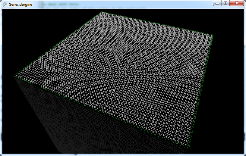
The planet in GenesisEngine is fundamentally represented by six square, flat quad-trees. Well, they start out as flat then become spherical somewhere along the way. If the camera gets too close and we need more detail than we have, we can split the quad into four equal pieces and repeat the following process for each one of the sub-quads. I’m not talking about the quad-tree subdivision in this post so all you really need to understand is that the planet starts out as a box, like this:

If we get a little closer each of the quads get split into four sub-quads, like this:

The green border lines indicate the area of the original quad and the red border lines indicate boundaries between sub-quads, which helps us keep track of where we are when things go spherical-shaped later on.
Quad grid space
The first coordinate system we have to deal with is what I named “quad grid” coordinates, which is simply the integer column and row of the vertex on the quad. This is a column-major system so the first number gives you the horizontal location and the second number gives you the vertical location. See the next screenshot below which makes the triangles and the vertices that define the triangles a little clearer. (I disabled updates for this shot in order to get in closer without having the quad split.) Each quad has a square grid of 65 by 65 vertices and the triangles are simply lines drawn between them. So a vertex starts life with an identity that says, “I’m the vertex on the 23rd column and the 37th row of this quad.” It doesn’t matter how big or small or how many levels deep the quad is because it’s all relative to the quad itself.
Unit plane space
However, the quad doesn’t exist in total isolation. It is a member of a group of 1..N quads that make up one of the six faces of the planet, so the next step is to describe this vertex in terms of where it is relative to the face. I called this coordinate system the “unit plane” system. Let’s define the face to have a extent from –1 to 1 in both directions, so 0,0 is exactly in the center of the face. (I guess that’s technically not a unit plane because it’s two units wide and long, but oh well.) Each quad has a certain position on that face and so does each of its vertices.
In the case where we haven’t split the original quad then the extents of the quad are the same as the extents of the face, from –1 to 1 in both directions. So the coordinates of the upper left vertex on this quad are -1, 1 and the lower right is 1, -1, and the rest of the vertices are evenly distributed in 64 equal steps between those extremes in both directions.
In the case where we have split the quad into four sub-quads, each of them covers one quarter of the face. (Refer to the sub-divided picture above.) So if we examine the upper left quad and consider its upper left vertex, it’s “unit plane” coordinates would be -1, 1 as with the parent quad but its lower right vertex would be 0, 0, which also happens to be the coordinates of the upper left vertex of the lower right quad.
It’s actually slightly more complicated in practice because we have six faces each facing a different direction in 3D space. The vertices in “unit plane” space are actually 3D vertices that describe a cube two units wide, long, and deep. For each face, two of the three x-y-z components vary to describe the locations on the face and the other is fixed at 1 or –1 as appropriate. 0,0,0 is the center of the cube (i.e. the center of the planet). These numbers are unitless so far and would be the same for planets of any real-world size.
Unit sphere space
Now that we have our vertices laid out in nice, evenly spaced rows and columns across our faces, it’s time to get spherical. Conceptually it’s not difficult to transform our vertices from box-like to sphere-like; we just bulge out the middles of each face and/or pull in the edges and presto, we have a sphere.
There are a couple of ways you can do the math here. The most straightforward way is to to take each vertex in “unit plane” space, treat it vector, and convert it to a unit length vector. Tada, instant sphere. This works ok but results in triangles of uneven sizes over the extents of the face. There is a better conversion algorithm that requires a bit more math but gives a nicer result and doesn’t cost that much more relative to everything else that’s going on. Follow the link to learn more about that.
Ok, so now we have our vertices transformed to “unit sphere” space, as in the picture below:

Planet space
Now it’s time to start thinking about real-world sizes. How big do you want this planet to be? In GenesisEngine the convention is that one unit in “planet space” coordinates represents one meter of length. To convert from “unit sphere” coordinates to “planet space” coordinates we simply multiply the vertex vector by the desired radius of the planet in meters. If we want to do varied terrain heights, which we do because that’s kind of the point of this project, we would add the terrain height at this location to the planet radius before multiplying with vertex vector. Now we have a lovely full-sized planet.
Mesh space
Up to this point all of the math has been done using doubles. Now it’s getting close to the time when we have to convert all of these numbers into a mesh we can render, but this is where we run into our issue with significant digits. We’ve done all of this work to get beautifully precise numbers that describe every elegant rise and fall of our terrain. We don’t really want to dump them into the meat grinder of 32-bit floats.
The trick here is to temporarily change the origin point of the vertex data so that the origin is exactly in the center of each mesh, or to say it another way, we’re going to translate the geometry of each quad down to the planetary origin so that the overall range of numbers isn’t so large. This puts us into “mesh space” which is the same as “planet space” except that the planet is now disassembled and all of its individual quads are jumbled up on top of each other at the center of the planet. We also remember where each quad mesh is supposed to be located on the planet’s surface so we can reconstruct it in its proper location later.
What good does that do us? I said above that merely changing the order of magnitude of our coordinate system doesn’t help us with the significant digit problem, which is still true. What we’re doing here is something different; we’re keeping the order of magnitude of the coordinate system the same but we’re collapsing the range of values we need to express into just a small part of that range, which reduces the number of significant digits we need to express them.
Think of it this way: how many significant digits do we need to express the number 12,464,297? Eight digits, too many for a float. But what if we subtract out the 12,000,000 part and hold it somewhere off to the side? How many significant digits do we need to represent 464,297? Only six digits, which does fit in a float. That doesn’t solve anything if you’re talking only one big number but if you have 65 x 65 = 4,225 big numbers, all of which are relatively close to the same size, then you can subtract some appropriate big number from all of them and be left with 4,225 small numbers to deal with.
Rendering big numbers without big numbers
Ok, once the vertices are translated into “mesh space” we finally have numbers that both (indirectly) represent the real world and are suitable for storage in floats. We can build our vertex buffers from these vertices and send them to the graphics card.
But the mesh data we send to the graphics card is all jumbled up in the same small area. It’s not planet-like, so how do we reconstruct the planet? We could set our world matrix to translate each XNA mesh back to where it’s supposed to be but that kills our precision. Well, this is where we play a coordinate-system trick with the camera. Instead of moving the view frustum around in our real-world coordinate space, we keep the view frustum fixed at the origin point and we rotate and translate every piece of geometry in the world around the view point. It’s kind of like driving down the freeway and imaging that your car is fixed in space while the earth spins beneath it.
How does that solve our problem? Well, any geometry that’s close to the camera is going to be rendered close to the origin (i.e. using small numbers) on the graphics card, so those vertices won’t blow the float digit budget. Any geometry that’s far away from the camera will be rendered far away from the origin (i.e. using big precision-losing numbers) on the graphics card but that doesn’t matter because they’re far away and small. Rounding is ok if the viewer isn’t close enough to see the damage.
Specifically, we take a mesh that’s encoded to be centered around the origin, and we get its original location relative to the center of the planet (which is still stored in doubles). We also get the location of the camera in real-world space (also stored in doubles). We subtract the camera location from the original location of the mesh which gives us the location of the mesh relative to the camera (in “camera space”, I guess), and that tells us how much we need to translate the encoded mesh away from the real-world origin in order to appear in the view frustum exactly the same way it would appear if both the mesh and the view frustum were where they were supposed to be in real-world space (which they’re not).
The end result is that all of the numbers stored in 32-bit floats never represent full coordinate values in the world. They only represent differences from some reference value. We can manipulate the reference value to tell us where we need to tell the graphics card to draw the geometry such that everything appears to be in its proper place, even though to the graphics card itself the perspective is quite different. The important numbers (the ones we see up close and personal) always stay relatively small while in float form and everybody’s happy.
As I said, it’s complicated.
Agile Makes Problems Visible
(I originally posted this on my MSDN blog.)
It’s often been said that agile project management techniques aren’t a silver bullet that will magically solve all of your problems. In fact, their biggest strength lies is not in solving problems, per se, but rather in exposing your buried problems and making them visible so you can deal with them. For a team switching to Agile it can feel like things are getting worse, not better, but that’s often because they’re being made aware of pre-existing problems they didn’t know they had. It may not seem like it but this is actually a good thing.
Here’s a real-world example. My current team of six people was recently assembled to build tools for an internal customer. I and one other member have a decent amount of experience with agile approaches but the rest of the team does not. I suggested that everyone read the free ebook Scrum and XP from the Trenches and think about whether they wanted to try that approach. Everyone readily agreed that our situation seems tailor-made for Scrum so we decided to go with it.
Our team manager did everything right to prepare for our first sprint planning meeting a few weeks ago. He made sure we had a clearly identified product owner, a product backlog of user stories, and he even printed out each story on a separate sheet of paper and taped them up all over a long whiteboard so we could discuss each one and write notes around them and on them as we made our plans. I was quite impressed.
We started the meeting and after getting through the preliminaries we turned our attention to the first user story on the backlog. The idea was that we were going to talk through about 20 stories to get a feel for the overall strategic direction of the project but within a few minutes we went off the rails. The conversation between the team and our product owner went something like this (not exact quotes, obviously):
“So the first story says the users want to enter information about avails into the system. That information includes these six fields . . .”
“Wait, why those six fields? That doesn’t make any sense. I thought three of them were part of rights, not avails.”
“No, that’s part of avails. An avail means [these things].”
“Dude, that’s not what avail is. You’re mixing it up with rights, and maybe pricing rules, too.”
“What?!?!? Then what the hell is an avail?”
We spent most of our three-hour meeting getting bogged down in the definition of terms and concepts, not getting anywhere near the original goal of walking through all of the stories. At some point during a painful, aggravated silence our team manager gave me a look that said, “Ok, now what, Mr. Agile Genius? You said this was supposed to work. We were supposed to finish this meeting with a sprint plan and that ain’t happening.”
I raised my hand and said to the room, “Ok, point of clarification here. Right now it feels like this process isn’t working, right? We’ve been going around in circles for two hours because we’re not all using the same language. There are several deep misunderstandings that are preventing us from making progress. However, the sprint planning process is doing exactly what it’s supposed to be doing. It made us get together in the same room, talk to each other, and discover that we still have some groundwork to do before we can can even have this planning conversation. The Scrum process didn’t cause this problem, just just exposed the problem. Not having a shared understanding of the domain concepts is a problem no matter what process you use. It’s far better that we discover this problem right here, right now, rather than write a 50-page spec and do three months of dev work around broken concepts before we realize we’re going in the wrong direction.”
Fortunately we were able to work through that particular problem and come to agreement on a shared vocabulary by the end of the meeting. We’ve had a couple more rough spots crop up since then but in each case we’ve identified the source of the problem, solved the problem, and moved on. Progress has not been as quick or as smooth as we imagined it would be but that’s not because Scrum isn’t working for us; it’s because we had a lot of problems to work through and those problems were being made visible quickly so we could identify them and solve them.
Software development is hard work. I doubt we’ll ever find anything that’ll change that. There are no silver bullets. But some processes are better than others for pointing you in the right direction and letting you know what problems you need to solve.
ASP.NET MVC 3, IDependencyResolver, and StructureMap
(I originally posted this on my MSDN blog.)
ASP.NET MVC 3 offers new facilities for easy dependency injection in various parts of the application that you might want to implement yourself. Brad Wilson discusses the new features in an extensive series of posts. In the Beta version and beyond, the way you do this is by creating a class that implements IDependencyResolver and serves as an adapter to the IoC container of your choice.
I happen to like StructureMap as an IoC container so I thought I ‘d wire it up for use in ASP.NET MVC 3. IDependencyResolver isn’t exactly a complex interface to implement but being the properly lazy developer that I am I thought I’d look around on the web to see if anyone had already offered up an implementation for StructureMap. I found a few different blog posts that all had pretty much the same code (such as Brandon Satrom’s) so I grabbed it and dropped it into my application. I then tried to have one of my controllers pulled from the container and . . . met with utter failure.
Specifically, StructureMap kept insisting that it had no idea what I was talking about when my IDependencyResolver adapter asked for an instance of my TitlesController (i.e. container.TryGetInstance(serviceType) was returning null). The framework would then fall back to trying to create an instance on its own which would throw an exception because this controller was designed for dependency injection and didn’t have a parameter-less constructor.
This was particularly aggravating because all the implementations I found on the web seemed to be the same and apparently they were working for other people. I beat my head against this problem for, um, longer than I should have, I guess, until I finally found a email thread started by Jimmy Bogard on the StructureMap users list that clarified the problem for me. The issue is that while StructureMap’s Container.GetInstance() will create an instance of a concrete type without it being explicitly registered, Container.TryGetInstance() doesn’t do that. Container.TryGetInstance() will give up and return null if the type you’re asking for isn’t explicitly registered as a plugin type. Coincidentally, the very first thing I was trying to pull out of the container was a concrete type (my controller class). The existing implementations will work for registered interfaces but not for controllers which are requested by concrete type.
By the way, while researching all of this I ran across this thread in which Jeremy Miller points out that the original implementation of of IDependencyResolver.GetServices was wrong, too.
So here’s my IDependencyResolver implementation for StructureMap which takes StructureMap’s non-intuitive behavior into account and also tries to minimize the number of exceptions that have to be thrown and handled:
(UPDATE: I removed some registration code from the constructor that was causing confusion and probably wasn’t necessary (at least not for resolving concrete controller types, anyway.) If you need to resolve interface types, you’ll need to register them with StructureMap in your app’s registration code or maybe do it below in the constructor.)
public class StructureMapDependencyResolver : IDependencyResolver
{
    readonly IContainer _container;

    public StructureMapDependencyResolver(IContainer container)
    {
        _container = container;

        // TODO: if you haven't registered necessary interfaces somewhere else, you'll need to do so here.
    }

    public object GetService(Type serviceType)
    {
        if (serviceType.IsClass)
        {
            return GetConcreteService(serviceType);
        }
        else
        {
            return GetInterfaceService(serviceType);
        }
    }

    private object GetConcreteService(Type serviceType)
    {
        try
        {
            // Can't use TryGetInstance here because it won’t create concrete types
            return _container.GetInstance(serviceType);
        }
        catch (StructureMapException)
        {
            return null;
        }
    }

    private object GetInterfaceService(Type serviceType)
    {
        return _container.TryGetInstance(serviceType);
    }

    public IEnumerable<object> GetServices(Type serviceType)
    {
        return _container.GetAllInstances(serviceType).Cast<object>();
    }
}
GenesisEngine: The Task Parallel Library Is Great But Threading Can Still Bite You
(I originally posted this on my MSDN blog.)
The new Task Parallel Library in the .Net Framework 4.0 is intended to simplify the process of adding concurrency to your application and it does a great job of it. I’m really impressed by how well it hides the mechanics of threading and lets you reason declaratively about what you want to do, not how it needs to be done.
My real-time engine, um . . . wasn’t
In GenesisEngine, I had a serious need to do some background processing. As you move around in the world the engine dynamically generates appropriately-detailed quad nodes based on where you are, and generating the terrain meshes for those nodes takes a lot of CPU work. Previously I was splitting nodes into more detailed ones on the main game loop thread during the Update pass and it caused a lot of stuttering in the frame rate. In fact, if you were close the surface you basically couldn’t move in real time; you had to turn updates off, move the camera, turn updates back on, and wait for the detail nodes to be generated for your new location. Yeah, it pretty much sucked.
Clearly it would be desirable to have all of that expensive node splitting and mesh generation happen on a separate thread. First, my laptop has two CPU cores and one of them was just sitting there idle. My desktop machine at work has four cores so three of them were twiddling their thumbs. The future is multi-core so let’s get on that train; ok, we need concurrency.
Second, I’d like the the game engine to continue to draw smoothly with whatever quad nodes it has at the moment and then later pick up more detailed nodes as they become available. I don’t want the draw loop to be delayed at all by waiting for nodes to be split. That means that not only does the node splitting need to be concurrent but it also needs to be asynchronous.
The Task Parallel Library to the rescue
Ok, so that didn’t sound like fun. I’ve written a decent amount of threading code from scratch in my time and while the principles are fairly straightforward the details can be an absolute killer. I wasn’t looking forward to doing it again in GenesisEngine so, being a properly lazy developer, I decided to wait until I could use the Task Parallel Library to do it for me. Once Visual Studio 2010 was out and the XNA 4.0 CTP was released, I had all the pieces in place to fix my problem. Many excellent articles have already been written on how to use the TPL so I won’t bother with a general tutorial; I’ll just present a walkthrough of how I used it to solve a specific problem.
First, let’s look at the code I was trying to make concurrent and asynchronous:
private void Split()
{
    var subextents = _extents.Split();
    foreach (var subextent in subextents)
    {
        var node = _quadNodeFactory.Create();
        node.Initialize(_planetRadius, _planeNormalVector, _uVector, _vVector,
                        subextent, Level + 1);
        _subnodes.Add(node);
    }
    _hasSubnodes = true;
}
The Split() method is pretty straightforward:
- Divide the extents of the node into four smaller extents.
- Creates new child nodes for each sub-extent.
- Add the new nodes to the list of children.
- Set a flag indicating that it now has children.
The strategy for the new implementation using the Task Parallel Library is pretty similar:
- Divide the extents of the node into four smaller extents.
- Create four tasks to run asynchronously and in parallel. Each task will create one child node.
- Create another task that will run when all of the first four tasks have completed. This task will add the new nodes to the list of children and set flags indicating that that split is finished and the node now has children.
private void Split(DoubleVector3 cameraLocation, DoubleVector3 planetLocation)
{
    var tasks = CreateBackgroundSplitTasks(cameraLocation, planetLocation);
    CreateSplitCompletionTask(tasks);
}

List<Task> CreateBackgroundSplitTasks(DoubleVector3 cameraLocation, DoubleVector3 planetLocation)
{
    _splitInProgress = true;
    var subextents = _extents.Split();
    var tasks = new List<Task>();
    foreach (var subextent in subextents)
    {
        var capturedExtent = subextent;
        var task = Task.Factory.StartNew(() =>
        {
            var node = _quadNodeFactory.Create();
            node.Initialize(_planetRadius, _planeNormalVector, _uVector, _vVector,
                            capturedExtent, Level + 1);
            node.Update(cameraLocation, planetLocation);
            return node;
        });
        tasks.Add(task);
    }
    return tasks;
}

void CreateSplitCompletionTask(List<Task> tasks)
{
    _splitCompletionTask = Task.Factory.ContinueWhenAll(tasks.ToArray(),
    finishedTasks =>
    {
        foreach (var task in finishedTasks)
        {
            _subnodes.Add(task.Result);
        }
        _hasSubnodes = true;
        _splitInProgress = false;
    });
}
The second implementation clearly has more code but considering what’s being accomplished here, it’s remarkably compact and elegant. In CreateBackgroundSplitTasks(), we first set a flag indicating that a split is in progress. This is so that when the main game thread does the next Update pass it won’t try to split the node again. Next, we use the StartNew() method of the TPL task factory to create and run tasks that create new nodes. The work that the task performs is defined in a lambda expression. Each task starts running immediately and independently in the background and will return a reference to the newly-created node when it’s done. Finally, CreateBackgroundSplitTasks() returns a list of all of the tasks it started.
How does the node know when all of its children are created and it’s safe to draw them? For that we create a fifth task that is dependent on all of the previous four. In CreateSplitCompletionTask() we use the very handy ContinueWhenAll() method of the TPL task factory to create another task that will only run after all of our node-creation tasks have completed. This task puts all of the created nodes into the child list and sets some flags indicating that the split is finished and that the node now has children.
The great thing about the TPL is that nowhere in this code did I need to think about which threads are going to run which blocks of code, or how many threads I should start up, or even the mechanics of how the different threads should signal to each other. How many cores do I have on this machine? Don’t know, don’t care. It’s all very declarative in nature. It’s just, “Go away and do these four things in parallel as fast as you can, and when they’re all done, do this fifth thing.” That’s it.
But!
You still have to think about the consequences
Using the TPL does NOT give you a get-out-of-jail-free card. The TPL lets you elegantly express your good concurrency intentions but, as they say, the road to hell is paved with just such.
If you read both versions of Split() above you’ll notice that the TPL version does something that the single-threaded, synchronous version did not: after a node is created, we immediately call Update() on the node. It took me quite a while to infer the need for that.
When I first wrote the concurrent implementation it seemed to run and generate child nodes ok but there was occasionally a strange artifact where a recently split node wouldn’t be drawn correctly at first, leaving a black hole where it was supposed to be. The artifact didn’t happen for all new nodes, only a few, and it only lasted for one frame so it was difficult to see exactly what was going on. I eventually deduced the problem by carefully reasoning about the possible interleaving of operations in the parallel implementation.
Due to the way the synchronous implementation was written, newly-created nodes were guaranteed to be updated before they were drawn. This didn’t happen in Split() but happened later in the update pass so it was kind of an implicit contract. In the parallel implementation, on the other hand, there was no particular guarantee that a new node would be updated before being drawn the first time. It turned out that due to timing the background split operation would usually complete between the draw and update passes so it would get updated in the next pass and then drawn, and everything was fine. Sometimes, however, the background split would complete after an update pass but before a draw pass, and thus would be drawn without ever having been updated. The code didn’t crash in this case (it would have been easier to debug if it had), but it didn’t draw as expected either.
The fix was to ensure that each node gets both initialized and updated in the background task before declaring the split operation complete. The new nodes are updated with information that is slightly out of date but that doesn’t seem to matter in practice.
This was one of those tricky concurrency bugs that seems pretty trivial when I describe it in hindsight but it was pretty baffling when I first saw it. The lesson: the TPL lets you easily implement concurrency but it doesn’t (and can’t) free you from the responsibility of understanding all the myriad of potential race conditions, deadlocks, and other assorted multi-threading nastiness. Sorry, even if you have a nifty library to do the heavy lifting, you still need to understand what it’s doing under the covers and how it will impact your code.
Concurrency changes contracts
The asynchronous implementation created another problem I had to solve. Some of my unit tests started failing. It turned out this was because the tests were causing a node to split and then testing that the correct things happened (child nodes created, etc). The tests were originally written with the assumption that once the call to Split() returned, the post-conditions could be immediately asserted, but with the async implementation that was no longer true.
The fix here was to capture a reference to the split completion task and make it available to the unit tests so that they could initiate a Split then explicitly wait for the completion task to finish. This necessitated a bit of code in the QuadNode class that serves no other purpose than to aid unit testing but I don’t see any way around it. The contract of Split() changed when I changed its implementation. This aspect of the contract wasn’t expressed in the method signature but it changed all the same and required a corresponding change in the tests. This just emphasizes the point that you have to think about the consequences every time you pull out the TPL.
The TPL is goodness
The TPL is a very fine piece of work and it makes implementing concurrency and parallelism dramatically easier. Sure, I still ran into a few hiccups but that’s just the nature of the problem space. I was very pleased with the result after I was finished; I can now move around in GenesisEngine and the frame rate stays pretty smooth at all times. The splitting and merging of nodes happens in the background and will eventually catch up with my movements. The engine scales very well with additional cores; on a quad-core processor it’s about three times as fast at generating new terrain as it is on a dual-core. (The main game thread runs as fast as possible right now and takes up most of one core, leaving one core available for terrain generation on a dual-core processor and three cores available on a quad-core.) The right thing just happens magically.
There’s still a lot of work to do to make my implementation less naive. For instance, if a node split is scheduled in the background but the camera moves out of range before it happens, the split request should be discarded without actually doing it. Also, priority should be given to nodes that are currently in the viewing frustum so the user sees the maximum amount of detail at all times. The TPL isn’t quite magical enough to do all that for me but I expect it’ll give me the tools to do it in a compact and elegant way.
You Get What You Measure
(I originally posted this on my MSDN blog.)
I’ve been participating in more conversations internally about promoting a team-oriented culture at Microsoft. Microsoft has a strong individual-oriented culture which works well for many things but doesn’t work so well for agile software development. The question of paying (at least partly) based on team results rather than individual results came up, and it’s an interesting thing to think about.
Many groups at Microsoft strongly focus individual-contributor evaluations on individual results, not team or product results. For instance, a developer might be evaluated on the number of product features he delivered and the number of bugs found in his code. That’s understandable in the sense that that individual results are easy to define and easy to measure, but a huge problem in that there’s no guarantee that successful execution on a random collection of individual commitments will result in working software.
That is to say, all of the PMs can successfully write specs, all of the devs can successfully write code, and all of the testers can successfully find bugs, and yet the business fails to make money because the parts didn’t synthesize together into a cohesive whole. Of course when you get to the senior manager level you start to see commitments that explicitly say, “Ship a successful product,” but ICs don’t usually have that in their goals and aren’t incentivized to make decisions that might promote the “ship a successful product” goal at the expense of their own individual goals.
The root issue here is the general failure mode of all metrics. If you define a metric and evaluate people on it, then people will optimize for delivering on that metric. When your metrics represent only secondary attributes rather than your true core goal, then you’re at high risk of people optimizing in ways that actually hurt your core goal rather than help it. Metrics are useful in direct proportion to how closely they represent the core goal. At Microsoft, our core goal is to deliver successful software products. Our evaluation and compensation system ought to be tied as closely to that core goal as we can possibly get it.
Unfortunately our core goal is rather fuzzy. Well, I guess measuring achievement of the core goal is pretty straightforward but mapping the ultimate end result back to the individual contributions that people made to get you there is really, really hard to do in an objective, measurable fashion. When we try to solve that problem we inevitably end up measuring indirect effects rather than primary causes, which makes people optimize on the wrong things, and we’re right back where we started.
It would be great if we could come up with an evaluation and compensation system that would explicitly encourage people to stop and ask themselves, “What is the one thing I could do today that would have the greatest impact on shipping a successful product,” rather than asking themselves, “What did I write down in my commitments last summer that I haven’t done yet?” That difference in mentality may be subtle but it has far-reaching implications in behaviors and the choices we make.
Learn The Why, Not Just The How
(I originally posted this on my MSDN blog.)
In another conversation on an internal email thread, someone asked some newbie questions about Scrum daily standup meetings, like do they have to be every day or could they be done every three days or so? There were some good replies that encouraged the standard practice of daily meetings, then someone else mentioned that since his team sits together in one common team room, they communicate all day long and they’ve found the daily standup meeting to be not really necessary at all.
I thought that was a interesting point and replied:
That’s a good example of why it’s important to understand the goals that any given methodology is trying to achieve, not just the ceremonies that it uses to achieve them. The goal in this case is a short feedback cycle, shared understanding of what all team members are doing, and identification of the most important things to be working on right at this moment. The mechanism you use to achieve that is really beside the point if you’re able to effectively drive the goal. Scrum’s mechanism of the daily standup meeting is very effective for the vast majority of Microsoft teams who have individual offices. If you’re fortunately enough to have extremely high communication going on all day long, then sure, I can see how a daily standup would not be as important.
Anyone who tries to implement Scrum (or any other new methodology) without understanding the end goals and how the individual practices are intended to express those goals is pretty much doomed to failure. I suppose you can start out that way (I guess I did, come to think of it) but you can’t continue for very long that way. You have to understand the “why”, not just the “how”.
Time and time again when I see a person or a team who is fumbling along with agile practices (whether that’s Scrum, XP, TDD, design patterns, or anything else) and it’s not really working for them, it’s usually because people are just going through the motions they’ve read about without any real understanding of the principles, the philosophy, and the goals involved. There’s usually some cargo cult engineering going on. This causes at least two types of serious problems:
- Either they slavishly follow every detail of the methodology without considering the unique circumstances of their project and adapting certain aspects of the process to best fit what they need,
- Or they start slicing and dicing the methodology, throwing out whatever they don’t immediately like or whatever seems difficult to implement without having any sort of plan to accomplish the same goals by other means.
The Agile Manifesto calls for favoring individuals and interactions over processes and tools. No methodology should be followed to the letter without thought, but most methodologies have important, specific reasons for every practice they prescribe. The only way we can favor people over processes and still deliver working software is if we understand the “why” of our processes so we can intelligently mold them to fit our people.
Multi-task At The Team Level, Not The Individual Level
(I originally posted this on my MSDN blog.)
My current work environment is pretty typical of a lot of tools teams, IT shops, and similar groups; we have lots of relatively small projects to build and maintain. In fact, we have far more projects than we have people in each discipline (Dev, Test, PM). This obviously means that we don’t have the luxury of assigning individuals to one and only one project for long periods of time; we have to slice up our time and devote attention to multiple projects in turn. Given that’s the reality of our situation, though, there are still different ways we can go about doing that, some healthier than others. We can multi-task at either an individual level or at a team level.
Individuals
Multi-tasking at an individual level means that Joe is splitting his time between the Widget project and the Froberg project, while Sally is splitting her time between the Froberg project and the Walleye project. Every individual has a different portfolio of projects that they’re responsible for. The benefit of this strategy is that it gives us maximum flexibility to allocate scarce engineers in a way that seems to cover all the holes on paper. There are several very expensive costs, however:
- People rapidly shift from project to project which means that no one develops a deep and strategic understanding of any one project.
- Because people are always coming and going on a given project, it’s hard to develop a sense of team identity or to develop productive working relationships with colleagues.
- Individuals are often left to make their own choices from day to day about which project is most in need of their attention at the moment. There’s no strategic thinking about priorities or about how to spend the overall time budget of the group.
When we multi-task at an individual level, we often end up building plans for our projects that assume 100% allocation when that’s not really the case. For instance, say that we have work happening on the Widget project and the Froberg project at the same time. From a group planning and budgeting perspective, it might look like we have one team devoted 100% to Widget and another team devoted 100% to Froberg and that the work should be able to proceed in parallel. But in reality that’s not the case because Joe is double-booked for both projects. That puts him in an awkward position because now he has to decide on a day-to-day basis which is more urgent: Widget or Froberg. That decision isn’t being made by the project owners and it’s not being made strategically; it’s being made individually and tactically. Despite people’s best intentions, that kind of system usually devolves into a last-in-first out work queue, i.e. we work on whatever was most recently brought to our attention.
Teams
On the other hand, we could multi-task at a team level. In other words, we could build a stable, consistent Dev/Test/PM team that has explicit responsibility for both the Widget and Froberg projects, while another stable team has responsibility for Walleye and something else. We still have multiple projects that need to be worked on, and we still need to make priority decisions between them, but now the trade-offs are visible in the budgeting, planning, and strategic thinking realms. Say the team is working on a new Widget feature. Oops, we have an urgent Froberg bug that needs to be fixed! What’s the cost of handling that? Well, the cost is that we postpone the Widget project while the whole team shifts its attention to Froberg. Is it worth it? Maybe, maybe not, but now we can have a proper discussion about it. It’s very clear and obvious. You can’t just sneak it in under the radar.
The costs were there in the individual model, too – if Joe is working on Froberg today then by definition he’s not helping Widget make progress – but the costs were hidden. The individual model seems like it’s easier to work with in the short term because it avoids the hard priority choices but those choices still need to be made and it’s best if they’re made explicitly rather than on an ad hoc basis.
Agile Means Teams
Of course there are multiple agile project management methodologies that emphasize the team as the unit of work. Scrum prescribes a team, a backlog, and a sprint full of work that is locked. If something urgent comes up, it gets prioritized into the product backlog for the next sprint and everything else necessarily shifts down in the stack. The benefit and the cost are clear to everyone.
Kanban describes a similar system but emphasizes continuous single-piece workflow which is probably a better fit than Scrum if you’re juggling lots of small, unpredictable jobs across multiple projects. If something new comes up, slot it into the backlog and everything else gets bumped down. The team continually pulls from the top of the list and you can forecast a pretty accurate time to delivery for any point in the backlog.
Even groups who like agile methods and are trying to practice them sometimes have a hard time breaking the habit of treating the individual as the unit of work. Every time they slip back into that old habit everything gets much more unpredictable and velocity falls dramatically. It’s inevitable. The way to make agile methods work is to keep the team together as a cohesive unit and feed them the work you want the most. Don’t steal individuals for side projects. Multi-task at the team level, not the individual level.
(Whew, I wrote that whole post without once using the word “resource”. It was harder than it sounds! 🙂 )
When Is A Sprint A Failure?
(I originally posted this on my MSDN blog.)
Here’s another question that was asked on one of our internal distribution lists:
When do we consider a sprint to be a failure? I don’t know the answer and have no clue about it. We delivered 7 out of 9 stories we committed with all the release criteria, but we failed to deliver two stories due to under-estimation of the stories we picked. Is this a failed sprint?
This stirred an interesting discussion about sprint commitments, continuous improvement, estimation, retrospectives, and numerous other things. This was my contribution to the thread:
The phrase “sprint failure” in Scrum has a pretty specific meaning to a lot of people. It means that at some point before the end of the sprint, you realize that your sprint plan has gone so far off the rails that the best thing you can do is to abort the sprint before it’s completed and build a new plan.
What if halfway through your sprint you realize that you’re probably going to be able to deliver only 7 of your 9 stories? Should you abort the sprint at that point and plan a new one? I guess it depends on the specifics of the stories but almost always I’d say no. You’re a little off the plan but not drastically so. That’s not uncommon. Keep going, deliver value, and afterwards figure out if there are improvements you can make for next time.
The original poster is apparently not talking about aborting a sprint halfway through. He’s talking about working until the end of the sprint then labeling the results. I think he needs to define what he means by “failure” here. Does he mean, “we should reflect on what happened and look for opportunities to improve?” Sure, I agree with that, though I’d probably stay away from the term “failure” because it can be easily misunderstood. Does he mean, “there are negative consequences imposed on the team?” I emphatically disagree with that. Not delivering 2 of 9 stories is not an outcome that should be punished.
If it’s treated as something to be punished then I guarantee that the team will adopt counter-productive behaviors. In this case, they’ll probably just low-ball all of their commitments so that there’s very little possibility of failing to deliver. This doesn’t help increase efficiency and reduce waste, though, because there’s no learning and improvement going on, just self-defense strategies.
One of the potential weaknesses of Scrum is that it’s easy to get too fixated on the concept of a sprint commitment and whether you fulfilled or failed to fulfill that commitment. Some measure of predictability is important, sure. But no estimation technique is foolproof and you can waste an awful lot of time trying to perfect something that is inherently imperfect. Always remember that the goal is simply “good enough” estimation because estimation isn’t value, it’s just a means to an end.
I think this is one of the reasons why there’s been a lot of attention paid to Kanban and single-piece flow systems lately; because Kanban gets rid of the sprint timebox and all of the potential distractions that go along with it. I personally feel that Scrum and Kanban aren’t mutually exclusive and if you merge the best of both systems you’ll knock the rough edges off of both. (Some people use the term “Scrum-ban”.) One of the best influences Kanban can have on Scrum is to put the concept of a sprint commitment into its proper perspective, that is, it’s a device for short-term planning, nothing more. Relax!
The sprint retrospective is a powerful tool for change and improvement but it only works if you approach it from a positive perspective of “how can we become better?” rather than a negative perspective of “how badly did we fail?”.
Always beware the Law of Unintended Consequences. Whenever you’re working with a system that contains humans you’ll find that some things you implement for positive reasons end up having negative results because they reinforce the wrong behaviors. I think an over-emphasis on sprint commitments, and and insistence on labeling each sprint as a success or failure, is one of those things.
GenesisEngine: Listen To The Tests!
(I originally posted this on my MSDN blog.)
As I wrote last time, I made a bit of a mess in my GenesisEngine project by jamming too many responsibilities into one class. I’m working on straightening that out and ran across some interesting observations already. I’m not finished yet but I’ll share what I’ve discovered so far.
Performing the surgery
I decided to first separate the quad tree node responsibilities from the mesh generation responsibilities since there didn’t seem to be a lot of entangling between them and it appeared to be a straightforward exercise. It turned out that there actually was a fair bit of entanglement in the split/merge logic and the tests helped me identify that and sort it out. I’m a big believer in TDD and I’m still often surprised at how much clear feedback my unit tests give me about the quality of my design . . . if I take the time to listen!
Side note: as I’ve said before, I’m working on the GenesisEngine project and blogging about it in part because I wanted to provide some real-world examples that are a bit more complex and interesting than the typical toy problems you see in “intro to ” materials. The downside of real-world examples is that it’s a lot harder to paste in a bit of code that adequately illustrates what I’m talking about, since, well, it’s complex. I’ll do my best but if you’re really interested in understanding what’s going on you should probably inspect the diffs on GitHub or grab the code and study it.
So what happened? The first step in breaking up my SRP problem was to create a new QuadMesh class to handle the generation and management of the terrain mesh data. I moved the mesh code from QuadNode to QuadMesh and also created new QuadMeshRenderer and QuadMeshSpecs classes plus several other ancillary files. Once that was done I had to resolve several compiler errors because it turned out that QuadNode.Update() relied on the presence of the mesh data which was no longer there.
Here’s the original version of QuadNode.Update():
public void Update(TimeSpan elapsedTime, DoubleVector3 cameraLocation, DoubleVector3 planetLocation,
                   ClippingPlanes clippingPlanes)
{
    var cameraRelationship = GetRelationshipToCamera(cameraLocation);
    DetermineVisibility(cameraLocation, planetLocation, cameraRelationship.ClosestVertex);
    if (_isVisible)
    {
        if (clippingPlanes.Near > cameraRelationship.ClosestDistance)
        {
            clippingPlanes.Near = cameraRelationship.ClosestDistance;
        }
        if (clippingPlanes.Far < cameraRelationship.FurthestDistance)
        {
            clippingPlanes.Far = cameraRelationship.FurthestDistance;
        }
    }
    var distanceFromCamera = cameraRelationship.ClosestDistance;
    if (_isVisible && distanceFromCamera < RealWidth() * 1 && !_hasSubnodes
        && Level = RealWidth() * 1.2 && _hasSubnodes)
    {
        Merge();
    }
    if (_hasSubnodes)
    {
        foreach (var subnode in _subnodes)
        {
            subnode.Update(elapsedTime, cameraLocation, planetLocation, clippingPlanes);
        }
    }
}
The GetRelationshipToCamera() method returned a private CameraRelationship DTO, which looked like this:
private class CameraRelationship
{
public DoubleVector3 ClosestVertex { get; set; }
public DoubleVector3 FurthestVertex { get; set; }
public double ClosestDistance { get; set; }
public double FurthestDistance { get; set; }
}
The compiler errors were in QuadNode.GetRelationshipToCamera(). The basic idea here is that QuadNode used to be looking at the mesh data and figuring out the distance from the camera to the closest vertex and the furthest vertex, and then was using that data to do several things:
- Figure out whether the node is visible
- Set the clipping planes appropriately if this node is closer or father than the clipping planes already are
- Decide whether to split or merge the node based on the ratio of camera distance to the real-space width of the node.
Complications set in
Ok, so obviously the GetRelationshipToCamera method needs to move to QuadMesh because it’s inspecting the mesh data, and the CameraRelationship class needs to be promoted to public so it can be shared between QuadNode and QuadMesh. QuadNode.Update() would call QuadMesh.GetRelationshipToCamera() and use the returned CameraRelationship DTO as it has been before. Simple. I made those changes (among others) and got everything to compile. There was only one change to QuadNode.Update(), which now looked like this:
public void Update(TimeSpan elapsedTime, DoubleVector3 cameraLocation, DoubleVector3 planetLocation, ClippingPlanes clippingPlanes)
{
    var cameraRelationship = _mesh.GetRelationshipToCamera(cameraLocation);
    // Other stuff is the same . . .
}
I then looked at my failing tests. Hmmm. All of my specs related to splitting and merging were failing because the stubbed-out QuadMesh object was returning null from GetRelationshipToCamera(). That’s not going to work. To solve that, I would need to create a CameraRelationship object in the spec context, populate it with specific numbers that would cause QuadNode to make the correct decision, and configure GetRelationshipToCamera() on the QuadMesh stub to return it. That means I’d have to think really hard about what the numbers ought to be in order to provoke the desired behavior in each spec context. Yuck.
The good news is that I’m lazy and that sounded like a lot of work. Way too much work, in fact. I thought about it for a couple of seconds and remembered the golden rule of TDD: “If you have to work hard to write your tests, you’re doing it wrong.”
Laziness FTW!
Ok, what am I doing wrong here? I have QuadNode going out to QuadMesh, retrieving a bunch of data, and making decisions based on that data. What kind of decisions? The same ones I listed above:
- Is the node visible to the camera?
- Do the clipping planes need to be adjusted to include this node?
- What is the ratio of camera distance to the real-space width of the node?
These decisions all have something to do with the mesh data:
- The visibility of the node is determined by the mesh because while a quad node has a 2D area, a mesh has a 3D volume. A large mountain may stick up over the horizon and be visible.
- The clipping plane adjustments are determined by the mesh for the same reason: the mesh is 3D.
- The camera distance part of the ratio is determined by the closest part of the node, which again is determined by the 3D mesh.
It’s at about this point that I got a mental image in my head of my unit test suite as a grizzled old sensei glowering at me, saying, “Have you learned nothing! Leave me and meditate upon the design principles! Perhaps you will find wisdom.”
I was trying to violate at least two principles with my stupid approach. First, the Law of Demeter, or “only talk to your immediate neighbors.” QuadNode was reaching through QuadMesh into the CameraRelationship object to get data.
Second, the Tell, Don’t Ask principle, or “don’t ask for information you need to do something, ask the object holding the data to do it for you.” Rather than telling QuadMesh to make decisions based on its private data and inform QuadNode of the results as I should have done, I was grabbing data from QuadMesh, moving it to QuadNode, and making the decision there.
Mind your own business
Ok, so how to fix it? The fixes were pretty simple once I had the principles firmly in my mind:
- Ask the QuadMesh whether it is visible to the camera. It has all the information needed to make that decision.
- Forward the clipping planes to the QuadMesh and have it modify them if necessary.
- Have QuadMesh calculate the ratio of of camera distance to the real-space width of the node and return that number. (This is technically still getting data from QuadMesh but it’s data that’s easily stubbed out and I’m ok with this until I find something wrong with it.)
Here’s the new QuadNode.Update() method which properly tells QuadMesh to do work and make decisions on its behalf:
public void Update(TimeSpan elapsedTime, DoubleVector3 cameraLocation, DoubleVector3 planetLocation,
                   ClippingPlanes clippingPlanes)
{
    _mesh.Update(elapsedTime, cameraLocation, planetLocation, clippingPlanes);
    if (_mesh.IsVisibleToCamera && _mesh.WidthToCameraDistanceRatio < 1 && !_hasSubnodes
        && Level  1.2 && _hasSubnodes)
    {
        Merge();
    }
    if (_hasSubnodes)
    {
        foreach (var subnode in _subnodes)
        {
            subnode.Update(elapsedTime, cameraLocation, planetLocation, clippingPlanes);
        }
    }
}
There’s another interesting lesson here as well, derived from Tell, Don’t Ask: it’s ok to create public members on the class that are highly specific to questions that other classes need to ask, as long as doing so helps you to hide private information. The QuadMesh.WidthToCameraDistanceRatio is a very specific sort of property. If I were designing this class as part of a generalized public framework this wouldn’t be something it would occur to me to implement. But I’m not designing a public framework; I’m designing a highly specific set of application classes that work with each other to solve a problem. In this case my goal should be to keep as much information hidden as possible (in this case, like the distance from the camera to the mesh) and only expose answers to questions or processed information that answers a specific question. This reduces coupling, increases cohesion, and makes the code more flexible and maintainable in the long run.
Side node: I’m maybe still not getting to the heart of Tell, Don’t Ask, since I’m still querying properties on QuadMesh rather than sending commands to QuadMesh, but it’s the best that I understand how to do right now.
It’s just magical how good unit tests will guide you to quality designs and warn you away from bad designs if you take the time to listen. You’d think I’d get used to it after awhile but the novelty hasn’t worn off for me yet. It’s ridiculously awesome. I giggle like a kid every time I see it.
If you want to examine the diff or download the source as it is after this fix, you can find it here.
