Translation and Windows
Arbitration and Translation, Part 2
Building on yesterday’s post, I’m going to try to explain how Windows copes with machines with strange resource translations. I’ll use two examples in this post, one related to I/O
port resources and one related to interrupts.
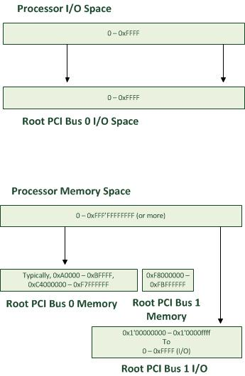
Just for convenience, I’ll duplicate the diagram from my last post, which diagramed the address space translations in a fairly complex multi-PCI-root machine.
Into such a machine, imagine that there’s a NIC plugged into the secondary root PCI bus and an UART plugged into the ISA/LPC bus, probably soldered onto the motherboard. The resulting PnP tree would look like this:

Of course, a fully populated PnP tree would be much more complicated. If you want to see the real thing, in full, look in Device Manager and choose “Show Devices by Connection.” (I took flack a few years ago for admitting that internally, we called this “Show as God Intended.” I still think of it that way, even though I understand why no user could use it that way.) Alternatively, you can see the same thing in the kernel debugger by typing “!devnode 0 1”.
For this example, assume the following things are true:
· The UART is not an ISA PnP device. It’s enumerated by the ACPI BIOS.
· The ACPI BIOS claims (through the _PRS object under the UART) that the device requires eight consecutive I/O ports, at one of several locations.
· The ACPI BIOS claims that the device can use one of two IRQs, 2 or 5.
· The ACPI BIOS contains a “control method” (labeled _SRS) which allows the ACPI driver to set the resources of the device.
· This device lies under the PCI root bus which is “Bus 0” in the example above. It has a native I/O port address space.
These things will cause the ACPI driver to respond to IRP_MN_QUERY_RESOURCE_REQUIREMENTS for this device with a structure that means “this device should be assigned one of three I/O port blocks which is eight bytes long and it needs one IRQ, which can be either 2 or 5, not shareable, edge triggered.”
For a full description on how this statement is constructed, see the documentation on IO_RESOURCE_REQUIREMENTS_LIST in the WDK. In short, I/O Resource Requirements lists are the “set of all possible sets of resources that a device could use.” For more detail on ACPI, see the spec.
As for the NIC, assume the following:
· It is a PCI device, not PCI-X or PCI Express. The upstream bridge is a PCIe to PCI-X bridge, which allows PCI devices to be plugged in.
· It has one PCI Base Address register and that BAR is of type “I/O,” implying that it must use the I/O address space. That BAR also implies that the registers of the NIC lie in a block that is 0x100 bytes long.
· It has a “1” in its Interrupt Pin register, implying that it will trigger its INTA signal with level-triggered semantics.
· This device lies under the PCI root “Bus 1” above. It has its I/O port space mapped into memory space.
These things will cause the PCI driver to respond to IRP_MN_QUERY_RESOURCE_REQUIREMENTS with “this device should be assigned one block of I/O ports which is naturally aligned and 0x100 bytes long. It can use any single IRQ, shareable and level-triggered.”
Upon receiving the response to these IRPs, the PnP manager starts trying to satisfy the requirements. To do this, it works its way toward the root of the PnP tree looking first for bus drivers which expose an “arbiter interface” for each device type. It also queries for a “translator interface.” I’ll cover arbiters in my next post. Today’s is really only about translators. But they’re somewhat intertwined, so I’ll define arbiters today as “something which knows about a specific resource type and knows the bus-local rules for deciding how these resources are allocated.” Allocating I/O ports on a PCI bus is different from allocating them on an ISA bus.
Once the PnP manager has searched to the root of the PnP tree, it will have found some interfaces.

The exact details have changed a little bit over the years and from release to release. I believe that I’ve accurately represented the state of affairs since Vista. Incidentally, you can see these in the debugger by typing “!translator” and “!arbiter.”
Translating from ISA to Interrupt Controller Input Pins
Since the ISA/LPC bridge devnode responded with an interrupt translator interface, the PnP manager needs to translate interrupts from ISA to the parent PCI. To really understand what this means, we need to have a little history lesson.
Thirtyish years ago, somebody at IBM decided that they were going to build a “personal computer” which had a single interrupt controller chip called the “8259 Programmable Interrupt Controller (PIC).” It had eight inputs. Each of these inputs was exposed in every expansion slot. The output pins were directly connected to the processor.
A few years later, some other guy at IBM designed the “IBM PC/AT.” When they built the AT, they used an 80286 processor which had a sixteen-bit expansion bus. They also added a few I/O devices. Since the expansion bus was wider, and since they needed more interrupt controller inputs now, they added a second 8259 to the machine. This second one was chained onto the first one. Its output pin was connected to IRQ 2 on the first one. Interestingly IRQ2 was still exposed in the older part of the expansion bus, so they connected that signal to Input 1 on the second PIC. So any old eight-bit device which was triggering the IRQ2 pin on the bus was actually going to cause IRQ9 to interrupt the processor.
Fast forward twenty-six or -seven years. We still have code to comprehend this, and it’s called a “translator interface for interrupts on the ISA devnode.”
The PnP manager invokes the translator from the ISA devnode and hands it two IO_RESOURCE_REQUIREMENTS, one saying “IRQ 2” and one saying “IRQ 5,” both edge-triggered and non-shareable. The ISA devnode modifies the first one to say IRQ 9. It leaves everything else alone.
The PnP manager keeps looking toward the root of the tree. The PCI driver really knows very little about interrupts. (This is because the PCI spec is nearly silent on the topic. Don’t get me started on how many years I’ve spent on filling that gap.) So the PCI driver doesn’t provide translator or arbiter interfaces for interrupts. The ACPI driver, on the other hand, knows quite a bit about interrupts, as the ACPI spec has quite a bit of text allowing BIOSes to describe the ways that the motherboard designer handled interrupts in a specific machine. So the ACPI driver exposes both interfaces.
The PnP manager, at this point, can stop translating interrupts from both devices because it has reached a common parent in the PnP with exposes an arbiter for interrupts. The arbiter is then invoked to choose which resources each device will be assigned. (Again, more on that in my next post.)
Translating from I/O Ports – Step 1
For both devices, the PnP manager starts looking for translators and arbiters for the device’s I/O port claims. It finds arbiters at the PCI layer, as PCI knows how to sub-allocate I/O port space to its children. Those rules are, thankfully, laid out quite clearly in the PCI spec, and aside from a few chipsets where the chipset designer didn’t think that the PCI spec applied to him, we can successfully figure out what configuration will work at that level.
Note that no translation has happened yet. We’re still talking about I/O ports as viewed on the buses which contain the devices, where the bus cycles will definitely be tagged as “I/O.”
Translation after Arbitration
Assume that for this example, the arbiters picked this set of choices:
UART: IRQ 9 and I/O ports 0x2040 through 0x2047
NIC: IRQ 11 and I/O ports 0x2000 through 0x20FF
No, that’s not a typo. Their I/O port claims actually seem like they overlap. This is fine, as they’re disjoint address spaces on different buses. (This can’t really happen on most PCs, but it can and does happen on some machines. See my last post.)
Now that the PnP manager has a resource assignment, it has to figure out how to present that choice to two separate audiences with two very different sets of needs. The first audience is the bus drivers. Now that we’ve chosen a resource set for each device, we need to program the devices so that they actually embody those choices. For the PCI device, this involves writing 0x2000 to its I/O BAR. For the LPC-attached UART, this involves executing the _SRS control method in the ACPI namespace underneath the UART device. Both of them need to be in bus-relative terms.
The second audience is the functional drivers, for the NIC and the UART. They don’t need to see the bus-relative view, as the driver can’t really directly generate bus traffic. The FDOs are made up of driver code running on the processor, so they need the processor-relative view of those resource claims.
To achieve that, I need to show you something we internally call the “checkmark diagram.” To truly understand this diagram, I have to apologize for the fact that, in house, all the PnP trees are drawn on whiteboards with the “root” at the top and the devices are leaves down at the bottom. This corresponds nicely with diagrams of physical machines where the processors and memory are at the top and the I/O devices hang down below like little appendages. The DDK/WDK tech writers convinced us that all public documentation should have the “root” of a “tree” firmly planted in the “ground.” Oh well.

I’ve already described steps 1 through 3. After arbitration, though, the PnP manager has to put these claims back in terms of the I/O bus. The only resource that went through translation on the way to arbitration was the IRQ for the UART. So now the translator interface from the ISA devnode reverses that process and changes that 9 back into a 2.
So the resulting “raw resource” assignments are now in bus-relative terms. They’re also now in terms of CM Resource Lists. Those are documented in the WDK, too. Again, in short, a CM Resource List is a single complete set of resources that a device either is using or could be using.
The raw resource lists for the devices are:
UART: IRQ 2 and I/O Ports 0x2040 through 0x2047
NIC: IRQ 11 and I/O Ports 0x2000 through 0x20ff
Lastly, the PnP manager goes back to toward the root of the PnP tree, passing the various resource assignments to any translators that may be at each node of the tree, trying to build a different CM Resource List, this time in terms of the processor.
The ISA devnode’s Interrupt translator immediately reverses itself again, and changes that 2 back into a 9. But there’s another interrupt translator in the tree, too, at the ACPI level. That translator is actually privy to some internal choices that the interrupt arbiter made, involving the IRQL and IDT entries (and in Windows 7 and later, IOMMU Interrupt Redirection Table entries) that the arbiter chose. So that translator can translate into processor-relative terms.
For the root PCI bus which maps its I/O Port space into processor memory, ACPI supplies an I/O Port translator interface. (It knows to do this based on contents of the ACPI namespace.)
Thus the “translated resource lists” for these end up looking like this:
UART: IRQL 11, Vector 0xb3, Affinity (target processor set) 0xF0 and I/O Ports 0x2040 through 0x2047
NIC: IRQL 10, Vector 0xa9, Affinity 0x0F and memory range 0x1’00002000 through 0x1’000020FF
Presenting Resources to Drivers
When all of this is complete, there are two CM Resource Lists in the PnP manager for the device. Both get sent as part of IRP_MN_START_DEVICE.
As explained in my last post, the driver contract is that the bus driver (or a bus filter like ACPI, sometimes) programs the device using the raw resources. The function driver calls MmMapIoSpace, IoConnectInterrupt, etc., using only the translated resources.
My next post will go into detail on what arbiters do.
- Jake Oshins