Arduino or Netduino: Sensor and Actuator, testing the circuit w/o CPU
When using your Arduino or Netduino to connect with the Web and then the “Cloud” you need to use the correct Write and Read requests. In this blog will use the Netduino only because it has a network connector on board, my Arduinos do not have a network connector, and there is a cost to getting one. I do have the Spark though and will get that working shortly. With sensors it is always a good idea to hook up the power, actuator and sensor without the CPU, reason? Well I learned from hard and expensive experience that if you hook up the CPU with the power and everything, the CPU often becomes an expensive fuse.
What is a fuse, we don’t use them much anymore, but a fuse is defined correctly as:
- Electrical circuit breaker: an electrical safety device containing a piece of a metal that melts if the current running through it exceeds a particular level, thereby breaking the circuit
In my experience one might also add:
- Electrical circuit breaker: an electrical safety device containing a CPU that melts if the current running through it exceeds a particular level, thereby breaking the circuit, and reducing the budget you have available to finish your sensor. So rule one for surviving the job you are on: Connect up as much as possible without the expensive stuff like the CPU so that you get what the whole idea behind the hardware is.
In this case we will use the CPU, in this case the Netduino, to measure a voltage variation when the series of articles are done, for this blog the Netduino is used to provide power via the micro-USB and the onboard voltage regulator.
Components:
- Software: VS 2013 Pro or Ultimate with the Micro Framework and correct firmware version for VS 2013

- Netduino Plus 2 with the network connector and micro-USB
- Sensor:
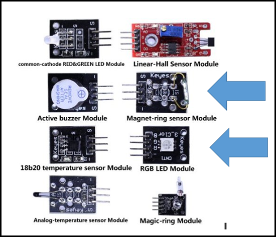
- Keyes Magnetic-ring Sensor Module (From the SunFounder 37 sensor kit)
- Optional: Use a push button instead of the Magnetic-ring Sensor Module
- Actuator (LED):
- Keyes RGB LED Module (mine has a burned out Red LED, so it is a GB LED Module)
- On my Keyes module the Green and Red are backwards
- Optional: If you don’t have the Keyes RGB LED Module, you can use any LED with the appropriate resistor
- Resistor:
- The Magnet-ring sensor Module has an unused 10K resistor on it, so I will use that one
Diagram
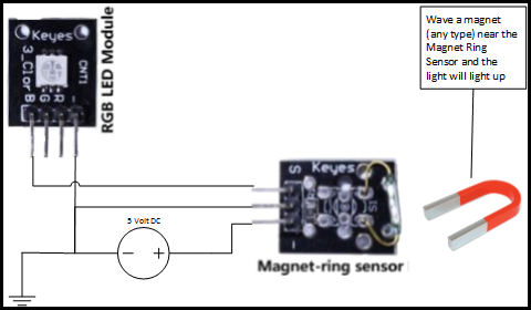
Here is the schematic, but it might be difficult to translate if you are not used to working with components, and in general you should draw out circuits even if you can visualize the circuit. Why? Circuits get complicated quickly, like software, but unlike software we have a way to implement the drawings.
Physical Schematic without the CPU in the circuit:
Diagram/Schematic (scroll down to see a physical like schematic)
The schematic is pretty simple, a switch connected to the LED through a 10K resistor. Remember that the Magnet Ring Sensor has a 10K resistor between the S-pin and the unmarked middle pin. To make the circuit work you do need a magnet to close the switch.
In a future blog I will include the Netduino to read the sensor and then connecting the Netduino to the cloud, then a simple app that you can use in the store.
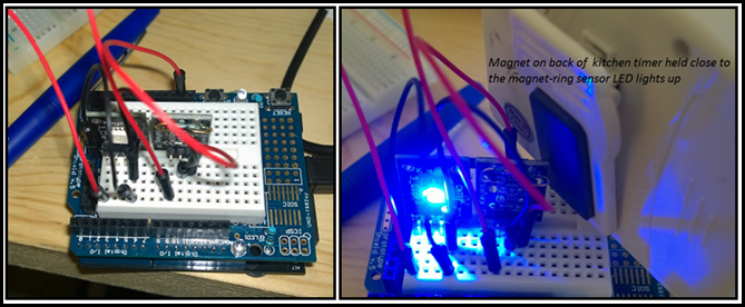
Here are the pictures of my lab, note that the Netduino is used to provide the 5 VDC, ground and mounting platform. I found a magnet on the back of a timer and used that to trigger the magnet ring sensor. This is a simple sensor by the way. However, it is widely used in manufacturing, automotive, refrigeration, security, and so forth.

