
Network virtualization using SCVMM and TFS/VSTS for your Build-Deploy-Test automation
In the previous blog post on How to perform Lab management operations in Build and Release, we explained about performing Build-Deploy-Test scenarios on your SCVMM environments using our TFS/VSTS SCVMM extension.
This post focuses on self service creation of isolated virtual networks using SCVMM and VSTS/TFS Build & Release.
Network Virtualization
Network Virtualization provides ability to create multiple virtual networks on a shared physical network. Isolated virtual networks can be created using SCVMM Network Virtualization concepts.
In this document, we will go through:
- Setting up Network Virtualization using SCVMM (one-time setup).
- Dynamically provisioning isolated virtual networks from TFS/VSTS Build & Release.
1. Setting up Network Virtualization using SCVMM
VMM uses the concept of Logical Networks and corresponding VM Networks to create isolated network of virtual machines.
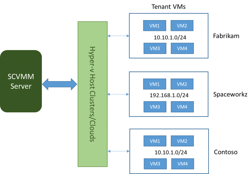
- You can create an Isolated Network of Virtual Machines that span across different hosts in a Host-Cluster or a Private cloud.
- You can have VMs from different networks residing in the same host machine and still be isolated from each other.
- You can define IP address from the any IP pool of your choice for a VM Network.
To achieve isolated networks using SCVMM, you need to ensure below prerequisites.
1.1 Prerequisites
- SCVMM Server 2012 R2 or later.
- Window 2012 R2 host machines with Hyper-V setup with at least 2 Physical NICs attached.
- One of P-NIC (say External) will have corpnet/internet access.
- The other NIC will be configured in Trunk Mode with a VLAN id (say 991) and routable IP subnets (say 10.10.30.1/24). You can get this configured by your network administrator.
- Ensure that Hyper-V hosts in one host group has the same VLAN id configured. This host group will be used for your isolated networks.
Once your prerequisites are completed, you can verify the setup working fine by following below steps:
- Open an RDP session into each of the host machines and open admin PowerShell session.
- Run the command: > Get-NetVirtualizationProviderAddress
 This command will get the provider address for the P-NIC configured in trunk mode with VLAN ID.
 - Now go to another host and open admin PowerShell session ping other machines PA using the command: > ping -p <Provider address>
 This test will confirm if all you host machines are connected to a PNIC in trunk mode with IPs routable across the host machines. If this test fails, please contact your network administrator.
 - Once the prerequisites are completed, you need to setup the Network virtualization layer from SCVMM admin console.
 This command will get the provider address for the P-NIC configured in trunk mode with VLAN ID.
 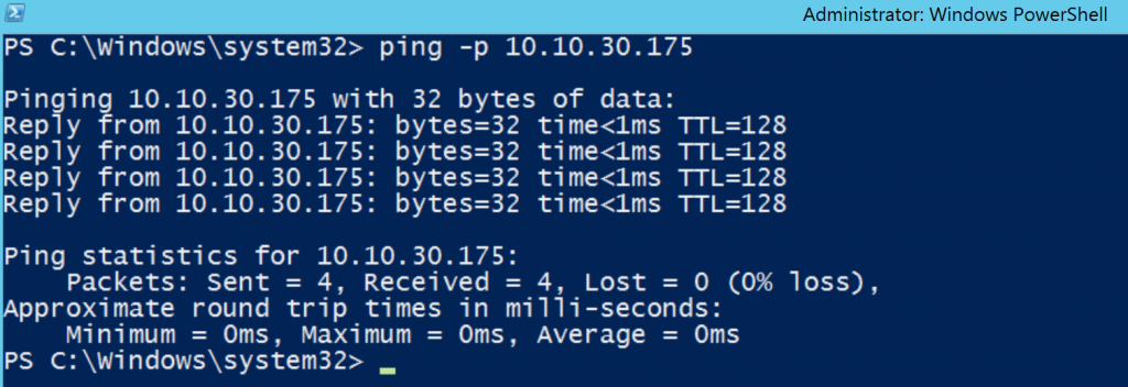 This test will confirm if all you host machines are connected to a PNIC in trunk mode with IPs routable across the host machines. If this test fails, please contact your network administrator.
1.2. Creation of Network Virtualization layer in SCVMM
Setting up of Network visualization layer in SCVMM includes creating Logical Networks, Port profiles, Logical Switches and adding the switches to Hyper-V Hosts.
1.2.1. Logical Networks:
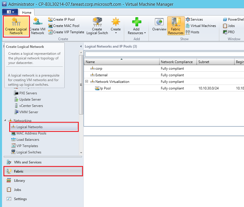
Login to SCVMM admin console.
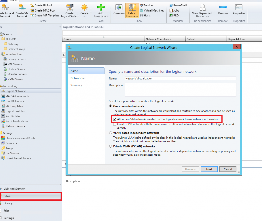
- Go to Fabric -> Networking -> Logical Networks -> Create new Logical Network.

- In the popup, give an appropriate name and select “One connected Network -> Allow new networks created on this logical Network to use network virtualization” and click on next.

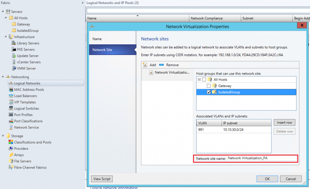
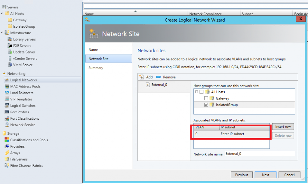
- Add a new “Network Site” and select the host group for which the network site will be scoped to. Provide the VLAN ID used to configure P-NIC in the Hyper-V host group and the corresponding routable IP subnet(s). For better tracking, you can change the Network site name below.

- Click on next and save.
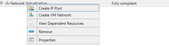
- Now Create an IP pool for the created logical networks and give a name and click on next.

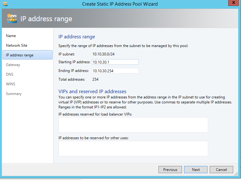
- Select “Use and existing network site” and click on next. Now provide the routable IP address range your network administrator has provided for your VLAN and click on next.
 If you have multiple routable IP subnets associated with your VLAN, then create an IP pool for each of them.
 - Provide the gateway address. By default you can give the first IP address in your subnet.

- Click on next and leave DNS and WINS and complete the creation.
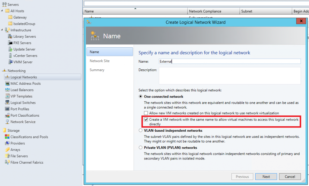
- Now create another Logical network for external internet access. But this time select “One connected network -> Create a VM network with same name to allow virtual machines to access this logical network directly” and click on next.

- Add a network site and select the same host group. But now add the VLAN as 0. This mean the communication uses default access mode NIC (internet). Click on next and save.
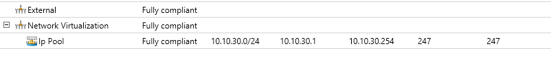
- Now this is how it will look in your admin console after creation of logical networks.

 If you have multiple routable IP subnets associated with your VLAN, then create an IP pool for each of them.
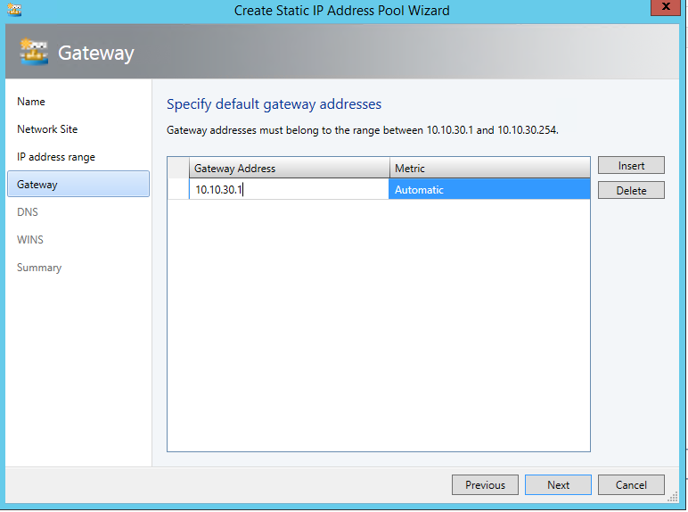
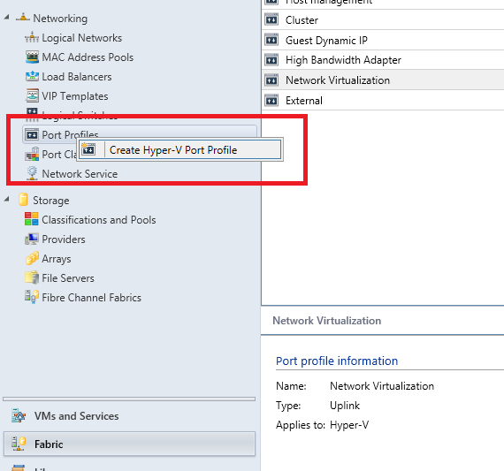
Now that logical networks are created you can go ahead and create Port profiles to be used by the networks.
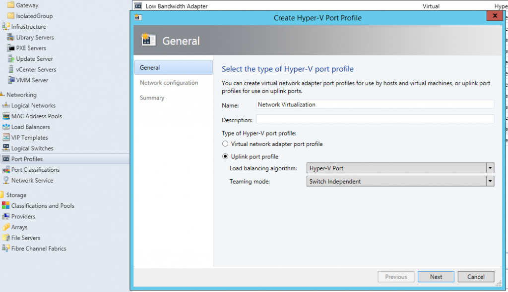
1.2.2. Creating Port Profiles:
- Go to Fabric -> Networking -> Port profiles and create a Hyper-V Port profile.

- Select Uplink port profile and select Hyper-V Port as Load balancing algorithm and click next.

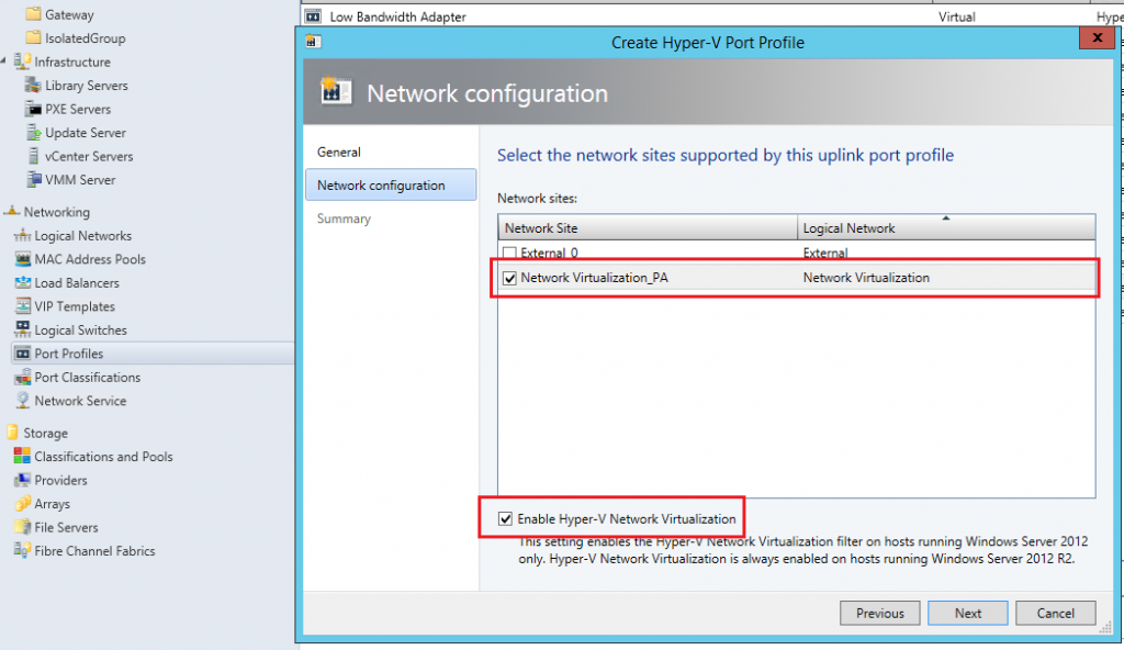
- Select the Network Virtualization Network site created previously and select “Enable Network virtualization” checkbox at the bottom and save the profile.
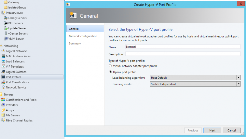
- Now create another Hyper-V port profile for external logical network. Select Uplink mode and “Host default” as the load balancing algorithm and click on next.

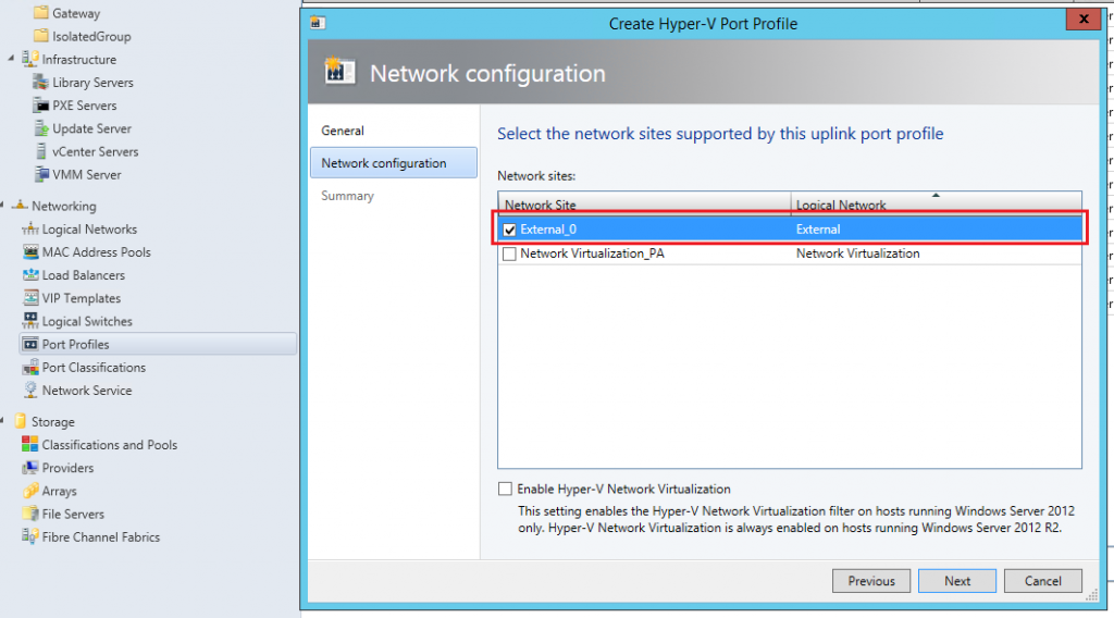
- Now select the other network site to be used for external communication and this time don’t enable network virtualization and save the profile.

Now that port profiles are created, you can go ahead and create Logical switches.
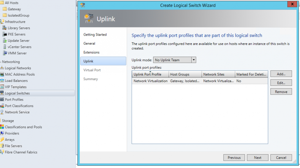
1.2.3. Creation of Logical switches
- Go to Fabric -> Networking -> Logical switches and create a logical switch.

- In the getting started wizard, click on next and give a name to the switch and click on next.
- Click on next and reach to uplink tab. Click on add uplink port profile and add the network virtualization port profile that you have created.
- Click on next and save the logical switch.
- Now create another logical switch for External network for internet communication. This time add the other uplink port profile you have created for external network.


Now that you have created logical switches, you can go to each of the host machines in your host group and assign the logical switches.
1.2.4. Adding logical switches to Hyper-V hosts:
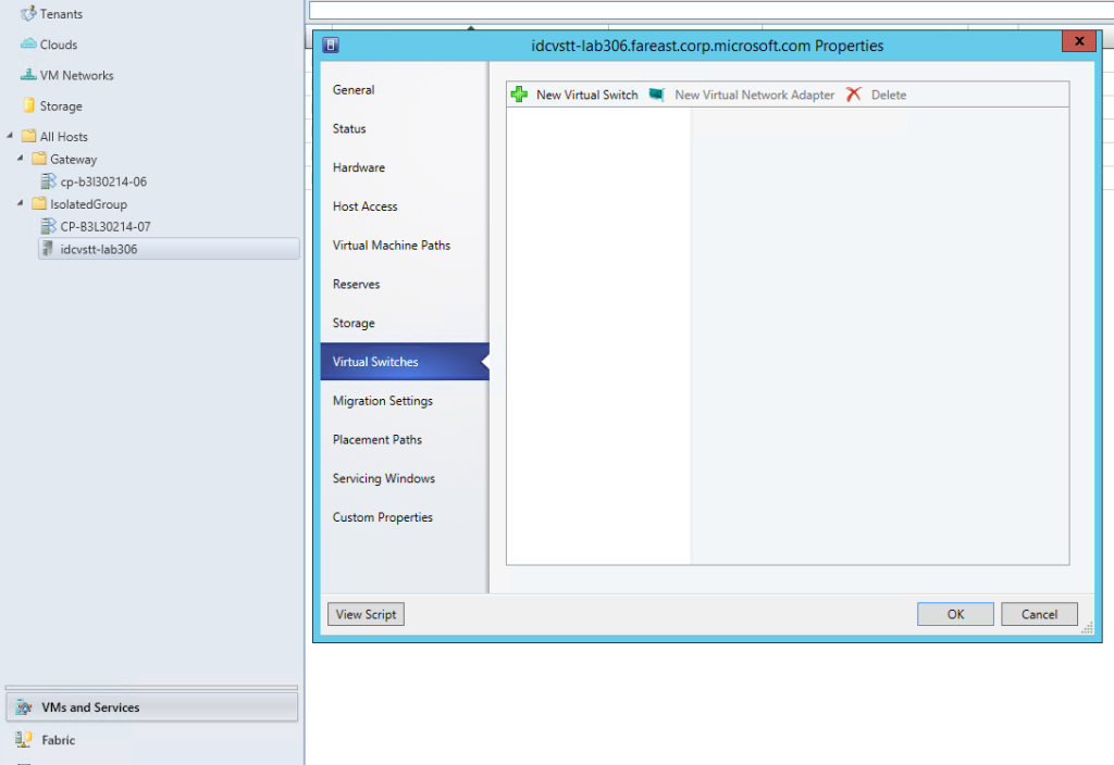
- Go to “VM and Services” -> Your host group -> each of the host machines. Right click and open “Properties” -> “Virtual switches” tab.

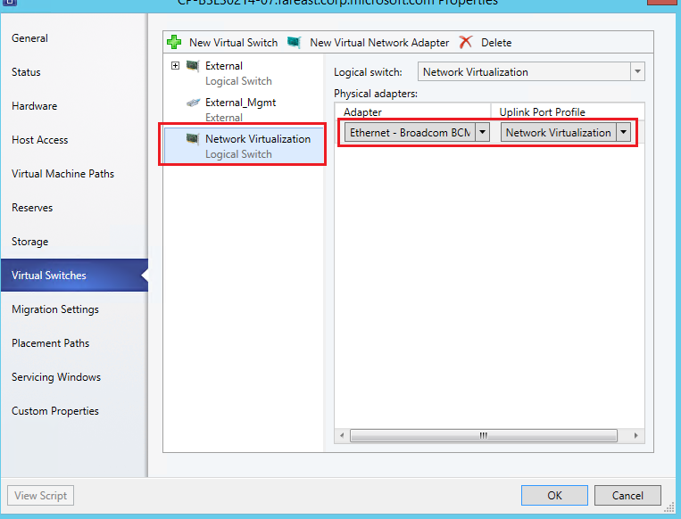
- Click on “New Virtual Switch” -> “New logical switch” for Network virtualization. Assign the physical adapter you have configured in trunk mode and select the Network virtualization port profile.

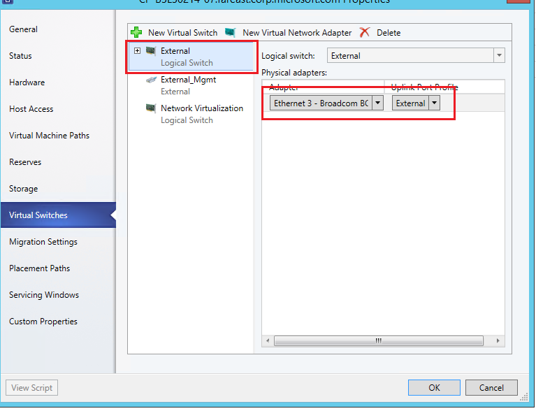
- Similarly create another logical switch for external connectivity and assign the physical adapter used for external communication and use the external port profile.

- Do the same for all the Hyper-V hosts in the host group.
Now that all your Machines are ready and Logical networks are setup, you can go ahead and create VM Networks for your Isolated networks.
The above setup is a onetime configuration for a given host group of machines. Once this setup is completed, you can dynamically provision your isolated network of virtual machines using SCVMM extension in TFS/VSTS Build & Release.
2. Dynamically provisioning isolated virtual networks from TFS/VSTS Build & Release
We provide a simpler way to create your isolated networks using SCVMM task in TFS/VSTS Build & Release. First thing you need to decide is the isolated network topology you want to create.
2.1. Network topologies
Isolated virtual networks can be broadly classified into three topologies.
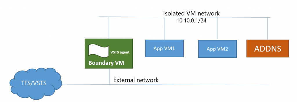
2.1.1. Topology 1: AD backed Isolated VMs.
- A Boundary VM with Internet/TFS Connectivity.
- A VSTS/TFS Deployment group agent installed on Boundary VM.
- An ADDNS VM if you would like to have a local Active directory domain.
- Isolated App VMs where you deploy and Test scenarios.
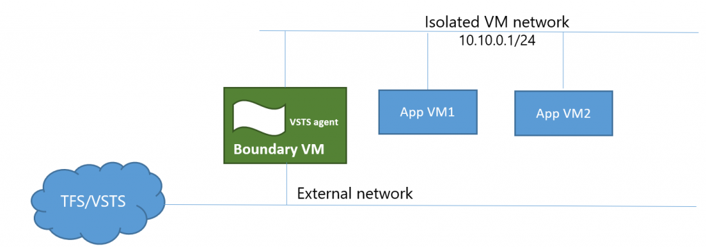
2.1.2. Topology 2: Non-AD backed isolated VMs.
- A Boundary VM with Internet/TFS Connectivity.
- A VSTS/TFS Deployment group agent installed on Boundary VM.
- Isolated App VMs where you deploy and Test scenarios.

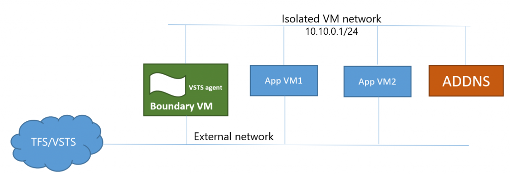
2.1.3. Topology 3: AD backed non-isolated VMs
- A Boundary VM with Internet/TFS Connectivity.
- A VSTS/TFS Deployment group agent installed on Boundary VM.
- An ADDNS VM if you would like to have a local Active directory domain.
- App VMs where you deploy and Test scenarios which are also connected to external network.
You can create any of the above topologies using SCVMM extension in Build & Release.
2.2. VM provisioning using SCVMM extension in Build & Release
- Open your preferred TFS/VSTS instance and install SCVMM extension if not installed already.
- Go to build/release definition and add a new SCVMM task.
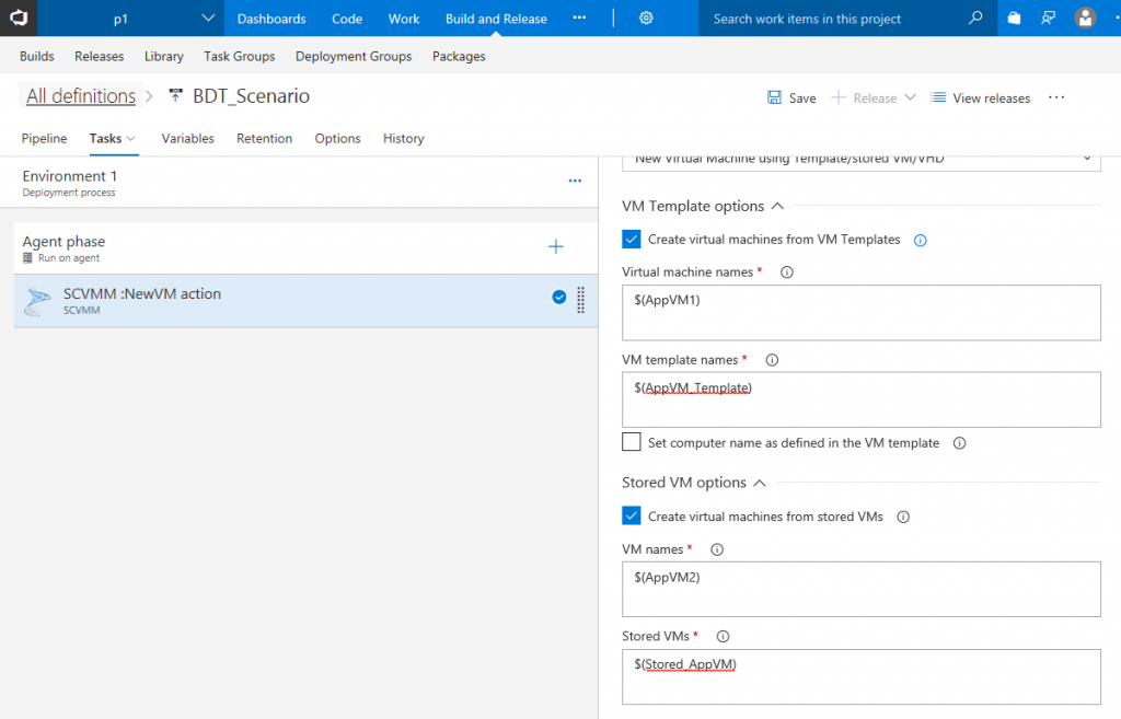
- In the SCVMM task, select an endpoint for the SCVMM server connection where you want to provision your virtual network and select “Create new Virtual machines from VM templates/Stored VMs and VHDs” option to provision your VMs.

- Provide list of App VMs you want to provision. You can create VMs from Templates, Stored VMs and VHD/VHDx. Choose the option of your choice and provide the VM names and corresponding source information.

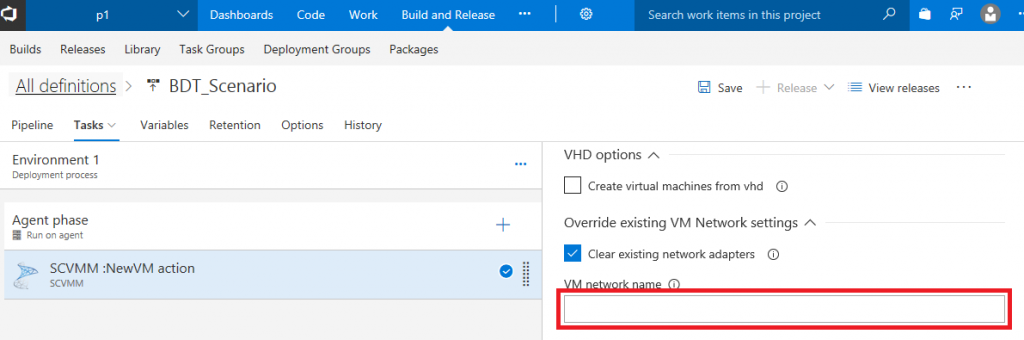
- In case of Topologies 2.1.1 & 2.1.2, leave VM Network option blank which will clear all the old VM networks present in the created VMs if any. For the topology 2.1.3, you must provide external VM network info here.

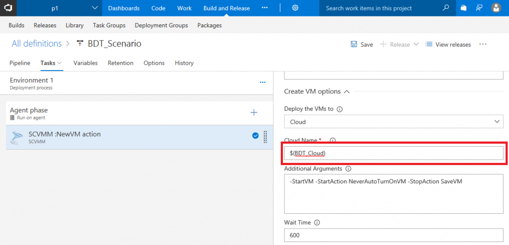
- Provide the Cloud/Host where you want to provision your Isolated Network. In case of private cloud, ensure the host machines added to the cloud are connected to the same logical and external switches as explained in 1.2.4.

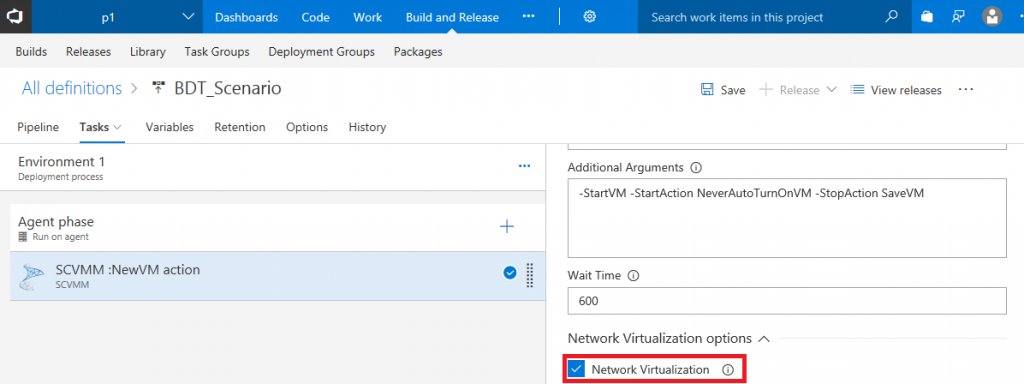
- Select “Network Virtualization” option to create your virtualization layer.

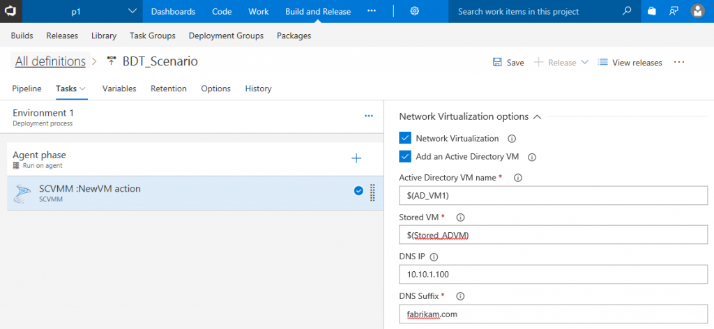
- Based on the topology you would like to create, you can decide if your network requires Active Directory VM. In this case we are trying to create Topology 2.1.1 “AD backed Isolated Network”. This will require Active directory VM.
- After selecting the Active directory checkbox, provide the AD VM name and Stored VM source. Provide the static IP address configured in the AD VM source and DNS suffix.

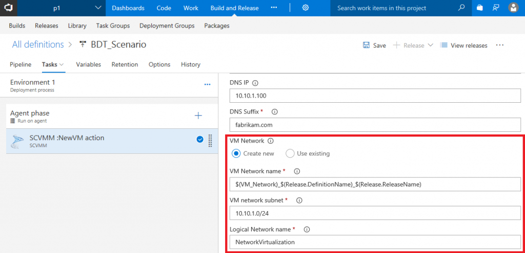
- Provide the VM Network and Subnet you want to create and the backing logical network you have created in 1.2.1 “Logical Networks”. Ensure the VM network name provided is unique. If possible append it with release name for better tracking.
- Select Boundary VM for communication with TFS/VSTS. This will be the entry point for external communication.
- Provide the boundary VM name and the source template. The boundary VM source should always be a VM template. And provide the existing external VM network created for external communication.

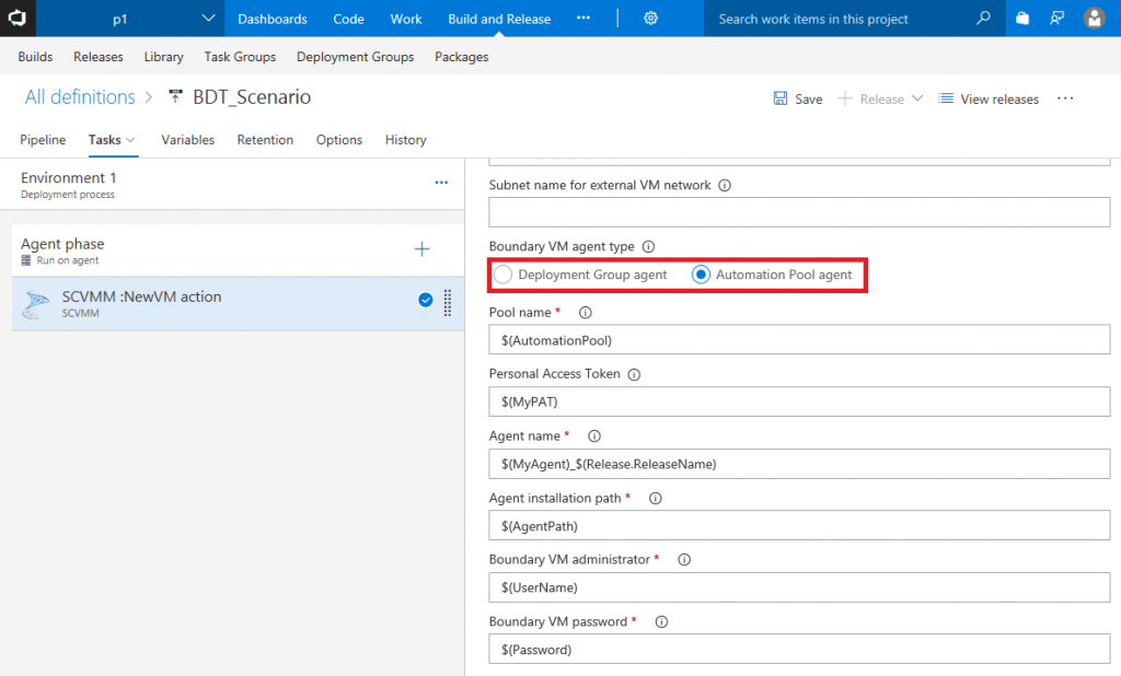
- Provide details for configuring Boundary VM agent to communicate with TFS/VSTS. You can configure a deployment agent or automation agent. This agent will be used in your BDT scenarios for app deployments.
- Ensure the agent name provided is unique. This will be used as demand in succeeding phase properties so that the agent will be picked up accurately. In case you have selected deployment group agent option, this parameter is replaced by Tag which should be unique as well.
- Ensure the boundary VM template has the agent configuration files downloaded and saved in the VHD before the template is created. And use that path as the agent installation path above.


This will create your isolated VM network. Once the network is created, you can use it for your app deployments and testing (BDT) scenario which is explained in the next steps.
2.3. Enabling your BDT scenario
- Create a new phase after your network virtualization phase.
- Based on the boundary VM agent (deployment group agent or Automation agent) created above as part of your Boundary VM provisioning you need to choose Deployment group phase or Agent phase.
- In the phase properties select the appropriate deployment group or automation agent pool.
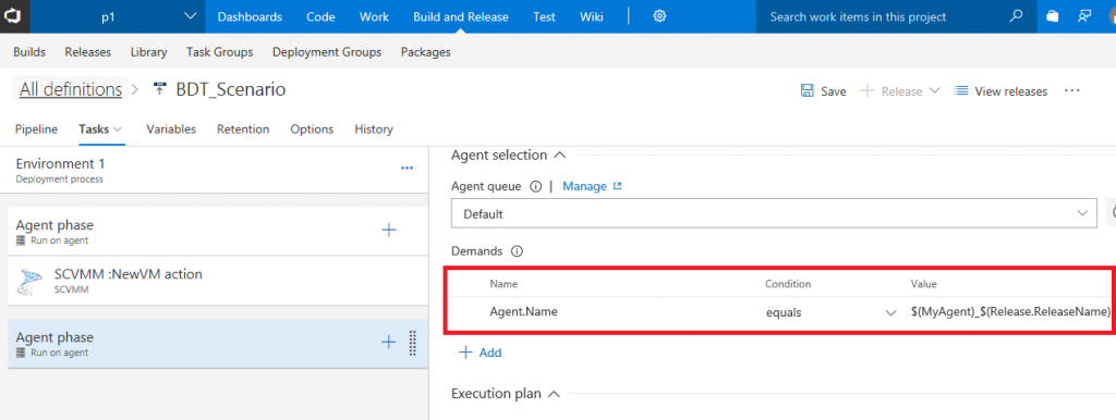
- In case of automation pool, add a new demand Agent.Name and provide the unique name provided in the network virtualization phase above. In case of deployment group phase, you need to set the tag in properties.
- Inside the phase add your tasks for deployment and testing.
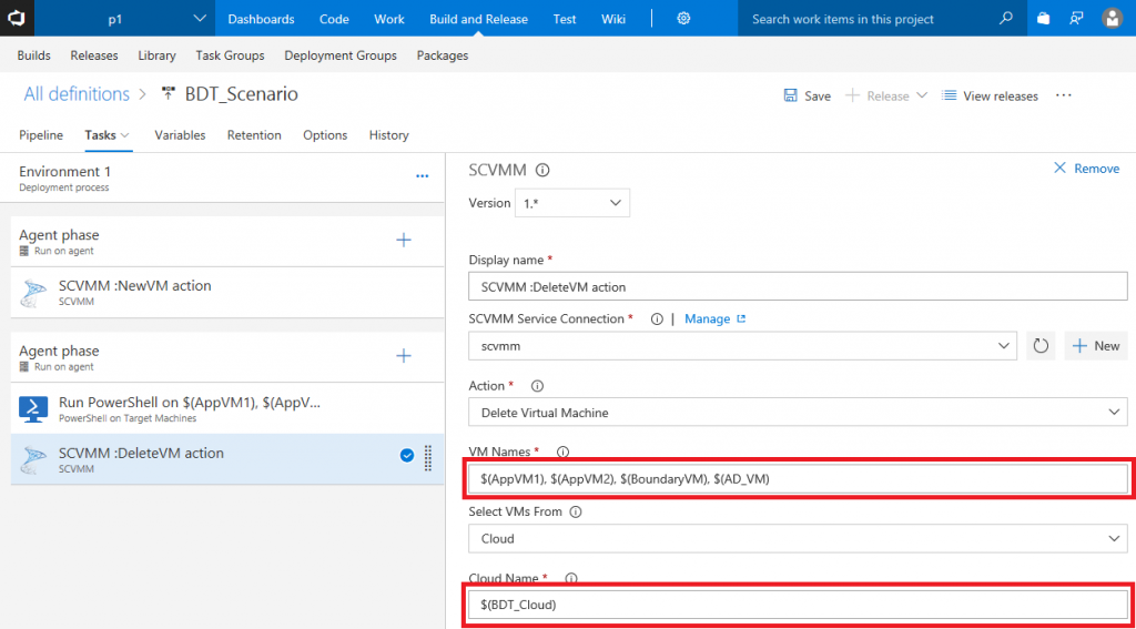
- After testing is completed, you can destroy the VMs using delete VM task.

Now you can create release from this release definition. Each release will dynamically provision your isolated virtual network and run your deploy and test tasks on the environment. You can find the your test results here in the release summary. And once your tests are completed, you can automatically decommission your environments. You can create as many environments as you need with just a click from Build and Release.
To summarize, our SCVMM task provides ability to perform lab management operations using Build and Release in a more efficient way. You can manage your SCVMM environments, provision your isolated virtual networks and perform your Build-Deploy-Test scenarios.
 Light
Light Dark
Dark
0 comments