The Formal Goodness of Agile Software Architecture – Part 2
In Part 1 of this short series I discussed an article that proposes the Intensional/Locality Thesis for formally distinguishing between what is Architecture and what is Design. Part 1 also covered how the Thesis has shaped my thinking about the role of the Architect and Software Architecture within an Agile project team.
As I was writing Part 1, specifically the bulleted lists of architectural specifications, it occurred to me that I had used a number of mechanisms on past projects to communicate Architecture. These mechanisms have included:
- Whiteboard conversations (my personal favorite)
- Word documents using text (my least favorite)
- Visio diagrams (OK, but lacks some rigor)
- UML models (another personal favorite)
It was towards the end of writing Part 1 that I decided that in fact there would be two posts – Part 1 describing how the Intensional/Locality Thesis reshaped my thinking and this post describing how to use UML models to communicate architectural specifications (in compliance with the Thesis) in an Agile way.
As I was thinking about the prep work for this post, I figured I would have to fire up Sparx and create a UML model to use as a case study. However, as I got prepared to do some modeling it occurred to me that I might already have something better.
A number of months back I created a sample UML model to illustrate one way that UML could be used for Software Architecture on an Agile project. The main goal of the sample was to illustrate how UML can be a powerful communication and documentation tool that enhances the agility of a team – how Architecture can be a point of leverage.
Intrigued by the reuse potential, I’ve decided to use this UML model to see how it stands up to the ideas discussed in Part 1. What follows in this post is the unaltered UML model I created, interpreted in the context of the Intension/Locality Thesis.
NOTE – There is a complete HTML representation of this UML model available from my SkyDrive. The link to the .ZIP is located at the bottom of this post.
The Conceptual View
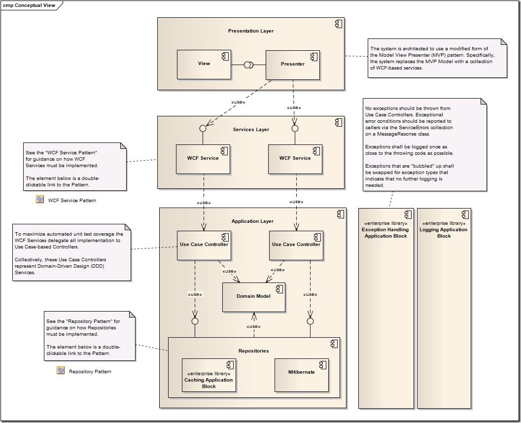
The first item of interest in the UML model is the Conceptual View. The intent of this model is to communicate the overall architecture of the software at a relatively high level of abstraction. While not 100% correct from a UML standards perspective, this model leverages the UML Component diagram as the means of communication. The Conceptual View is depicted below:
When using the concepts in Part 1 to interpret the model depicted above, we can quickly identify that the Conceptual View declares a number of architectural specifications. We can also identify that these specifications adhere to the two main categories described in Part 1:
- “Traditional” architectural specifications (e.g., Pipes and Filters)
- Design specifications (aka Patterns) that have been elevated to architectural specifications
The first thing that is worthy to note is that the Conceptual View prominently lays out the first architectural specification – the use of a Layered Architecture.
Additionally, the Conceptual View incorporates a large number of constraints on the structure of the software:
- The Presentation Layer depends upon the Services Layer
- The Services Layer depends upon the Application Layer
- The Application Layer depends on a Data Access Layer (DAL)
- The Application Layer depends upon the following:
- The Exception Handling Application Block of the Enterprise Library
- The Logging Application Block of the Enterprise Library
- The DAL depends on the following:
- The Caching Application Block of the Enterprise Library
- NHibernate framework
That’s a lot of architectural goodness derived from a single diagram, but is typical of the large amount of leverage I’ve seen in crafting architectures that are replete with Design Patterns.
As you might imagine, a full-blown collection of architectural specifications would likely include guidance on how Repositories should be implemented using NHibernate, how the Exception Handling Application Block will be configured, how the Caching Application Block should be used, etc.
For the sake of brevity the UML model isn’t 100% complete, but it does illustrate a very powerful mechanism that UML has for modeling architectural specifications – UML patterns.
Repository Architectural Specification
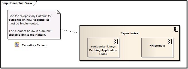
As the Conceptual View illustrates, there is an architectural specification for the use of the “Repository Pattern”. As covered in Part 1 of the series, I tend to think that one of the duties of the Agile Architect is transforming appropriate Design Patterns (which are inherently design specifications under the Intensional/Locality Thesis) into architectural specifications. This transformation is attained mainly through moving the scope of a Design Pattern from local to non-local. As illustrated in the Conceptual View, this transformation is embodied in the following subsection of the model:
The problem with this architectural specification is that it isn’t very clear to both the Developers and Code Reviewers/Code Pairs what this means in terms of the constraints on the structure of the software - even if the team is familiar with Repositories and has read Evans. That’s not so say there’s no value in the architectural specification as it stands (there is definite value in communicating the architecture at a high level), it’s just that if the specification could be enhanced it would become an even greater point of leverage for the team.
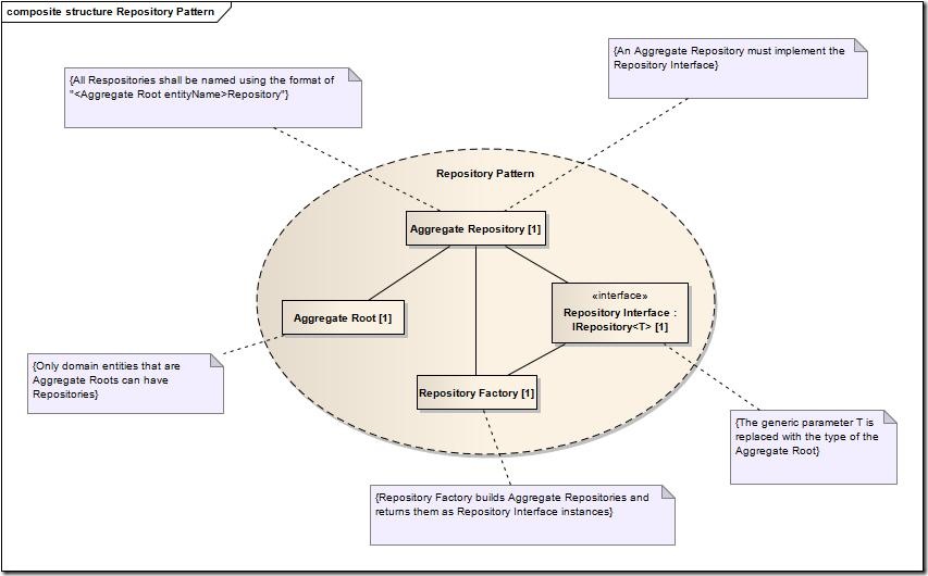
This enhancement can be accomplished very easily using the UML concept of a Pattern (some additional info is available here). Rather than bore you with the all the UML standards goodness, I’ll just pull the depiction from the model of the “Repository Pattern”:
As discussed in the Eden and Kazman article on the Intension/Locality Thesis, both architectural and design specifications concentrate on the definition of constraints on the structure of the software – they just differ on the scope of the constraints (the locality). The UML pattern specification above clearly illustrates this concept in the definition of the roles that constitute the pattern (e.g., “Repository Factory”) and constraints on those roles (e.g., “Only domain entities that are Aggregate Roots can have Repositories”).
What is particularly noteworthy in model above is that the pattern roles define a further constraint in terms of the use of a standard code interface (“IRepository<T>”). We’ll see the implication of this below.
As I discussed in Part 1, notice how this pattern does not specify to a Developer on the team which exact Aggregates, Aggregate Roots, and Repositories need to be built (e.g., Contracts, Customers, Orders, etc) – it only specifies only how these items should be built.
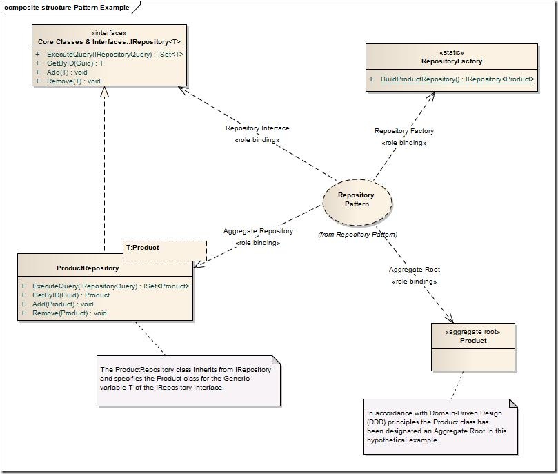
While this enhancement of the Repository architectural specification provides powerful leverage to the team, UML has one last enhancement to increase the power of Agile Software Architecture. The following model illustrates a hypothetical example of software that is in compliance with the Repository architectural specification:
As I described in Part 1, I would argue this model exemplifies the difference between Architecture and Design in an Agile project. I would also argue that the model above illustrates the differences between the Architect and Developer roles on an Agile project. Specifically, the model above illustrates that the Agile Architect is responsible for the definition of the architectural constraints of the software (Repository in this case). Additionally, the model illustrates that another role on the team identifies that a design is required for the concept of “Product” that complies with the architecture of the software – the Developer role on Agile projects.
NOTE – As I’ve wrote previously, the best Architects also craft software. As such, it is important to understand that Architects may bounce back and forth between the Architect and Developer roles on an Agile project – defining architectural specifications one day and delivery software in compliance with the architecture the next.
A second, more complex, example will hopefully cement these ideas.
WCF Service Architectural Specification
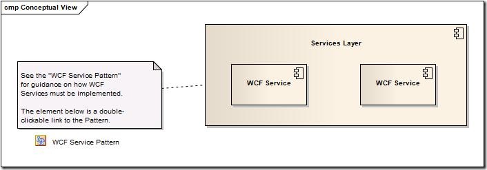
The Conceptual View of the software architecture identifies the usage of the “WCF Service Pattern” as an architectural specification. Specifically, the following subsection of the Conceptual View defines this architectural specification:
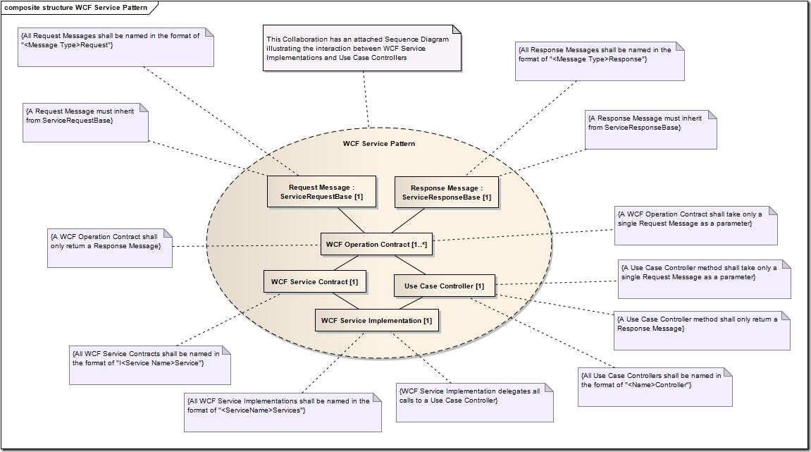
As we saw previously with the Repository architectural specification, the WCF Service architectural specification has a UML pattern specification:
While the WCF Service architectural specification is quite a bit more complicated than the Repository architectural specification, it is worthy to note that it again clearly segments Architecture from Design and segments the Architect from the Developer on an Agile project. Another thing that is worthy to note in the model above is the multiplicity constraint within the “WCF Operation Contract” role in the pattern. Specifically, this constraint specifies that every instance of the WCF Service architectural specification must have at least one instance of the “WCF Operation Contract” role, but there is no upper bound on the number of “WCF Operation Contracts”.
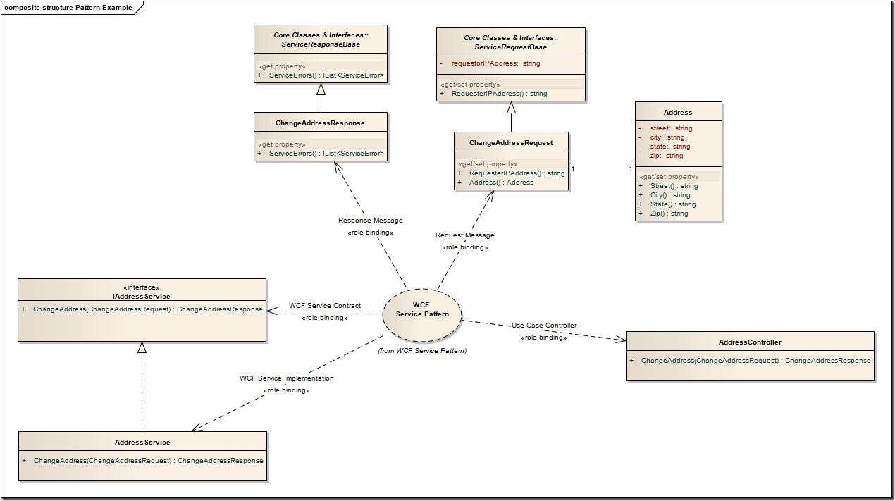
As with the Repository architectural specification, the WCF Service architectural specification also included an example instantiation of a design that is compliant with architectural spec. The model below illustrates this example design:
There you have it! Some very powerful examples of how to leverage UML for Agile Architecture that is compliant with the Intension/Locality Thesis.
Reusable Code Assets
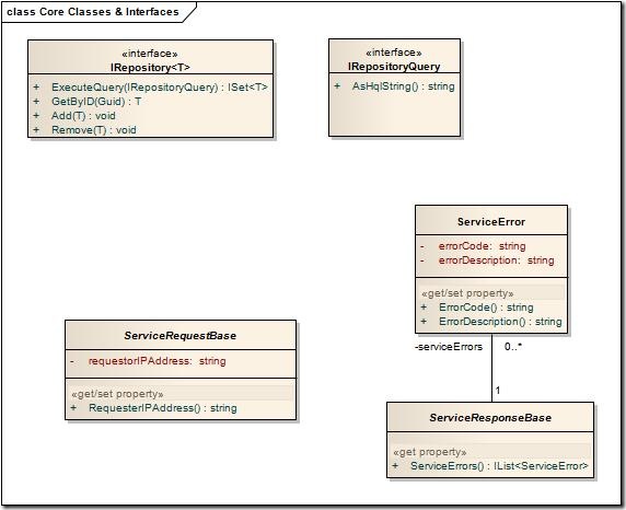
The above architectural specifications rely on some common reusable code assets as part of their constraints on the structure of the code. The following model illustrates the these assets from the UML model.
Don’t Fear UML & Software Architecture
Believe it or not, UML and Software Architecture are not antithetical to the use of Agile.
I’ve personally seen these tools and techniques succeed under both XP-like and Scrum-like (I use “-like” because I never seen a “pure” implementation – nor do I ever expect to ;-) methodologies. Typically architecture in these instances were a Sprint (or two 2-week XP iterations) at the start of the project, and then the architecture is iteratively addressed Agile-style throughout the project. Those of you who are in the know will recognize this as akin to some of the ideas behind RUP Elaboration.
I heartily advise giving this a try – your Developers will love you for it and it just might increase the fun you have as an Architect to boot!
Any feedback from Architects and Developers on this series would be greatly appreciated.
SkyDrive Files
