Windows 10: How to use IoT extension for Raspberry Pi 2 (part 2)
In the previous post we discussed how to add extensions to Universal projects and made a short overview to GPIO classes. Today I am going to continue the overview of the IoT extension and we will discuss I2C hub and classes there.
Last week I received MPU6050 sensor which provides data from gyroscope and accelerometer and is very useful for people who would like to build own drones and helicopters. You can find many different boards in the market including just 6050 chip. In my case I bought this one from https://robotshop.ca.
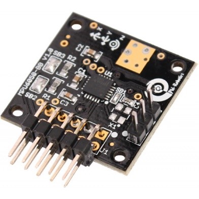
This sensor doesn’t require soldering and it contains 5V to 3.3V convertor (6050 chip uses 3.3V), which allows to use power from ESC or other boards with 5V power pins.
MPU 6050 uses I2C hub to communicate. So, to get the sensor ready to work you need to connect 5V and GND pins on Raspberry to VCC and GND on the sensor. Additionally you need to connect SDA and SCL pins there. This sensor doesn’t have any leds and it’s not easy to understand if everything is OK. So, the simplest way to check if it works is to start developing something.
All needed classes you can find in Windows.Devices.I2c namespace and the first one is I2cDevice. Each device, which you connect using I2C hub, should be associated with object of I2cDevice class and thanks to this object developers can communicate to device. The most common methods there are Read and Write which are working with array of bytes in order to receive or send data. But in many cases you need to send data to device to ask something and read response from there. In order to avoid calling of two methods, I2CDevice class supports WriteRead method. This method has two parameters as arrays of bytes. The first array contains data which you are going to send to device and the second one – buffer for data from device.
Thanks to I2cDevice, it’s easy to communicate with devices but in order to get reference to the I2cDevice object you need to accomplish several tasks.
First of all you need to get reference to I2C device on the board (not your sensor but existing I2C pins). Microsoft uses the same approach as for all other devices like Bluetooth, WiFi etc. You need to use friendly name to create query string for the device and try to find the device on the board. GetdeviceSelector method of I2cDevice class allows to create the query string and you should use I2C1 friendly name there. In order to find information about the existing device you should use FindAllAsync method of DeviceInformation class. This method returns information about available I2C device and you can use this information in order to create I2cDevice object. Next step you need to create connection string for your sensor. It’s easy to do using I2cConnectionString class passing address of the sensor to the constructor of the class. Once you have information about I2C on your board and connection string for external device/sensor you can create I2cDevice object using FromIdAsync method.
So, for my MPU 6050 I created the following code:
 class MPU6050
{
 //I2C address
 private const byte MPUAddress = 0xD2>>1;

 private I2cDevice mpu5060device;

 public async Task BeginAsync()
 {
 string advanced_query_syntax = I2cDevice.GetDeviceSelector("I2C1");
 DeviceInformationCollection device_information_collection = await DeviceInformation.FindAllAsync(advanced_query_syntax);
 string deviceId = device_information_collection[0].Id;

 I2cConnectionSettings mpu_connection = new I2cConnectionSettings(MPUAddress);
 mpu_connection.BusSpeed = I2cBusSpeed.FastMode;
 mpu_connection.SharingMode = I2cSharingMode.Shared;

 mpu5060device = await I2cDevice.FromIdAsync(deviceId, mpu_connection);

 mpuInit();
 }
}
mpuInit method there is sending initial values to the sensor and I will describe it below. MPUAddress should be 0xD2 according to documentation but we need to take just 7 bits of this value so I moved the value to one bit right.
Once we have I2cDevice object we can start to work with the device. It’s not so easy because MPU 6050 has lots of registers and you need to understand most of them. Additionally, you need to initialize the sensor to get values using needed scale range etc. Let’s see several registers there:
- 0x6B – power management. It’s possible to setup different settings related to power mode but the most important bit there is bit number seven. Thanks to this bit you can set the sensor to initial state;
- 0x3B – 0x40 – accelerometer data. There are 6 bytes which contain data for x, y and z axis. Because two bytes are required to present the data per each axis there are 6 bytes (not 3). So, to form result you need to use the first byte as a high part of short (int16) and the second one – as a low byte;
- 0x41 – 0x42 – two bytes which represent temperature there – high and low byte;
- 0x43 – 0x48 – 6 bytes for gyroscope data (as for accelerometer);
So, you can use mpuInit method to setup initial state of the sensor. For example, you can resent the sensor using the following command:
mpu5060device.Write(new byte[] { 0x6B, 0x80 });
In order to measure something you can use WriteRead method. I don’t want to create much code in this post, so I want to show how to measure temperature only. You can use the following code:
 byte mpuRegRead(byte regAddr)
{
 byte[] data=new byte[1];

 mpu5060device.WriteRead(new byte[] { regAddr },data);

 return data[0];
}
public double mpuGetTemperature()
{
 double temperature;
 short calc = 0;
 byte []data = new byte[2];
 data[0] = mpuRegRead(MPU_REG_TEMP_OUT_H);//0x41
 data[1] = mpuRegRead(MPU_REG_TEMP_OUT_L);//0x42
 calc = (short)((data[0] << 8) | data[1]);

 temperature = (calc / 340.0) + 36.53;
 return temperature;
}
Later I am going to publish my MPU6050 class on GitHub as well as some additional classes which you can use from C# in order to work with accelerometer and other sensor. Use my twitter @sbaidachni to get updates about it.