IoT: How to integrate two boards
In the previous posts I described some features of Galileo 2 board but there are still some scenarios, which may not be implemented on Galileo 2 boards only. For example, Galileo doesn’t have GPU, so you cannot use Galileo to output video. But there are several micro boards in the market like Raspberry Pi board, which supports GPU, HDMI output and allows to use camera as well. So, on the one hand we have a good solution with the Intel inside processor but on the other hand we still have some scenarios when we need to use several boards there. So, in this post I decided to show how to integrate two boards.
I used the Netduino and Galileo boards but this approach will work for Raspberry PI and Arduino as well. The idea is in using TX/RX pins, which are implemented in the most boards and allow to make serial communications. In fact, TX/RX pins is the same like COM1.
In order to test TX/RX pins I decided to build something like this
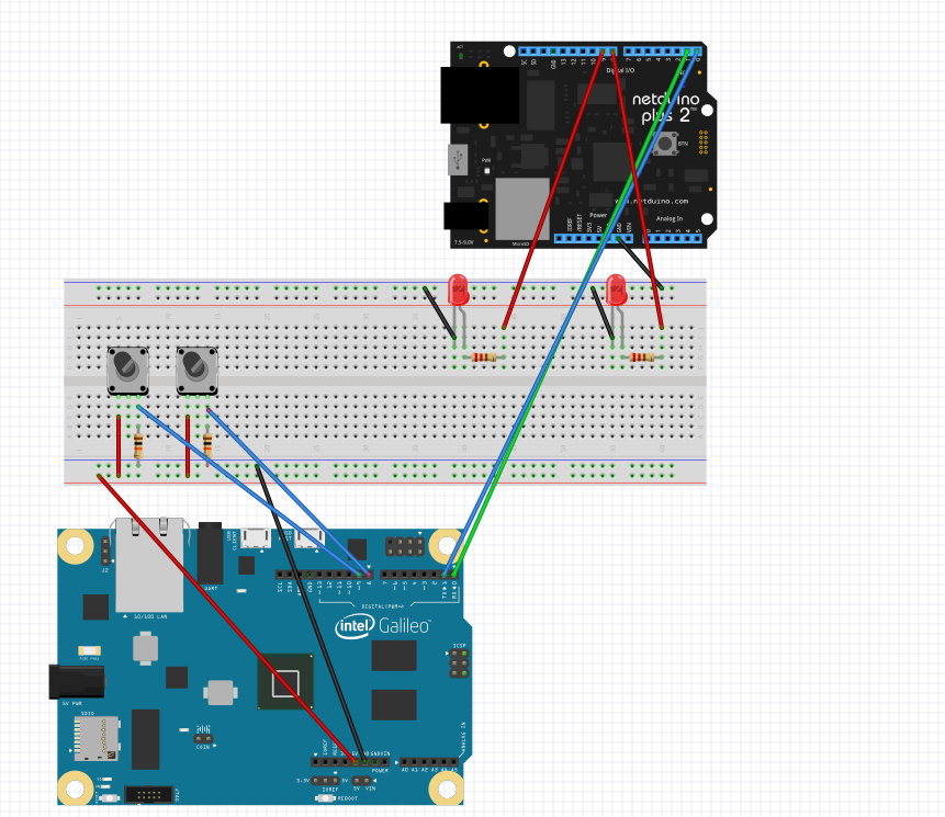
The idea of the project is too simple: we will use Galileo board in order to get input from two buttons and thanks to them we are going to control two leds, which are connected to Netduino. Because we use Netduino compatible boards, we can find TX/RX pins connected to pins 0 and 1. One of this pins is used for sending data and the second one – for receiving. So we should connect pin 0 (Galileo) to pin 1 (Netduino) and pin 1 (Galileo) to pin 0 (Netduino).
The code of our applications is pretty simple. In case of Arduino you can use the following example:
 public class Program
{
 public static void Main()
 {
 OutputPort ledRed = new OutputPort(Pins.GPIO_PIN_D8,false);
 OutputPort ledYellow = new OutputPort(Pins.GPIO_PIN_D9,false);
 SerialPort serial = new SerialPort(SerialPorts.COM1,9600,
 Parity.None, 8, StopBits.One);
 serial.Open();

 while(true)
 {
 if (serial.CanRead)
 {
 int b=serial.ReadByte();
 char c = (char)b;
 switch(c)
 {
 case 'r':
 ledRed.Write(true);
 break;
 case 'y':
 ledYellow.Write(true);
 break;
 case 'f':
 ledRed.Write(false);
 break;
 case 'h':
 ledYellow.Write(false);
 break;
 }
 }
 }
 }
}
This code just get the commands from serial port and switch on or switch of the leds.
In case of Galileo, you can use the following code:
  #include "stdafx.h"
 #include "arduino.h"

 int _tmain(int argc, _TCHAR* argv[])
 {
 return RunArduinoSketch();
 }

 int but1 = 8;
 int but2 = 9;
 bool flag1 = false;
 bool flag2 = false;

 void setup()
 {
 Serial.begin(CBR_9600, Serial.SERIAL_8N1);
 pinMode(but1, INPUT);
 pinMode(but2, INPUT);
 }

 void loop()
 {
 if ((digitalRead(but1) == HIGH) && (!flag1))
 {
 Serial.write('r');
 flag1 = true;
 Sleep(1000);
 }
 if ((digitalRead(but2) == HIGH) && (!flag2))
 {
 Serial.write('y');
 flag2 = true;
 Sleep(1000);
 }
 if ((digitalRead(but1) == HIGH) && (flag1))
 {
 Serial.write('f');
 flag1 = false;
 Sleep(1000);
 }
 if ((digitalRead(but2) == HIGH) && (flag2))
 {
 Serial.write('h');
 flag2 = false;
 Sleep(1000);
 }
 }
I used sleep there in order to avoid several inputs from one button click there.
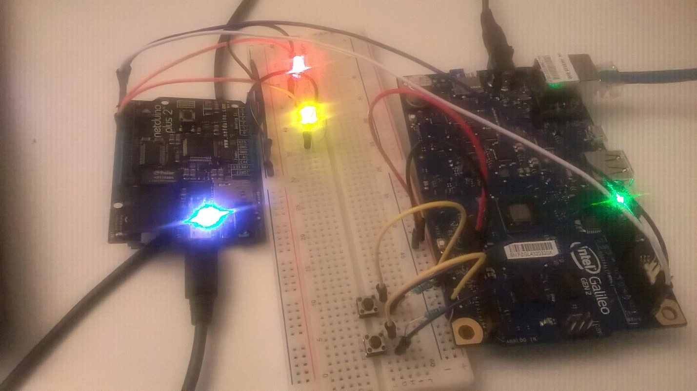
Finally I run my project:
In our case we used Galileo for sending data. But if you want to write some code which will able to receive some data you should add the following preprocessor directive to C/C++ configuration properties: SERIAL_EVENT; Additionally you should implement serialEvent method, which is called if some data is available.
You can use TX/RX pins in order to communicate with PC as well. In order to do it you can but UART->USB adapter which costs around 6 dollars (use just two pins there).