Internet of Things: My first experience with Galileo 2 (part 5)
When you are planning to build your own device you should think about power. In some cases it’s OK to connect your device to the nearest socket but for some projects it will not work. Just imagine a robot, which requires access to socket. So, we need to use independent sources of power like batteries.
In order to understand, which power supply is supported by Galileo, I visited Intel site and found the Galileo 2 datasheet there. According to it, Galileo 2 supports power supplies from 7 V to 15 V. So, in order to be power independent, simple 9V battery should be OK. So, I visited Fry’s Electronics and found the following components there:
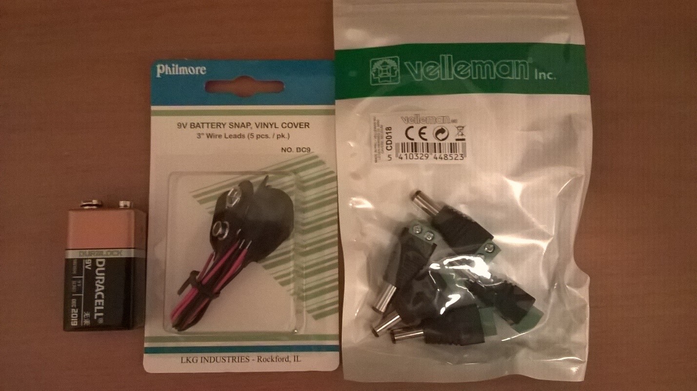
Finally, I spent about 2 minutes in order to assemble all components together and check that everything works fine. Right now I have an independent power supply and I may build something like a robot or a flying drone.
In order to build a robot you need to work with motors. There are three general types of motors: DC motors, Stepper-motors and Servos.
DC motors work based on electromagnetism and are used to rotate an axle continuously. You cannot control angle of rotation, so, usually this type of motors is using to turn wheels.
Stepper-motors allow to rotate axle step by step in fixed number of degrees. You should use this type of motors if you need good accuracy there. A simple example of Stepper-motors is second hand in many battery-powered clocks.
Servos are very popular in robotics because they are used in order to create joints. They cannot turn continuously but they can move to fixed number of degrees in both directions with great accuracy. Therefore in order to realize legs, hands, fingers etc. you will use servos.
Today I decided to make some experiments with a DC motor. Usually, DC motors have their own power supply, because they require more voltage than Galileo might give. At the same time we need a way to manage the source of external voltage in order to start and stop our motor. Of course, we may use relay and some components in order to do it or special motor shields but the best way is using a small control chip. This is L293D chip, which allows to control up to two DC motors.
I don’t like special motor shields, because they require a lot of space, they are expensive and limited to 2-4 motors. So, if you need more motors, you need to buy one more shield etc. In case of L293D, the chip is pretty small, cheap and you can put as many chips as needed on your breadboard.
In order to understand how the chip works, you need to find a datasheet in Internet. In general, the chip looks like this:
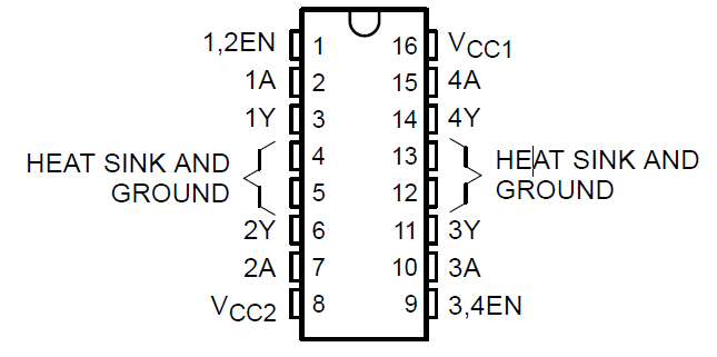
There are the following pins:
- EN, A pins – we should use them in order to control our DC motor. We may use them in order to start a motor turning right or left and stop it;
- Y pins – we should use them in order to connect our motor. Thanks to L293D, you may use motors with voltage up to 36V;
- VCC2 pin – it should be used for power supply. This power chip be used in order to start motor turning. So, in general, we will use external power supply there (up to 36V);
- VCC1 pin – the chip requires power as well in order to operate, so we will use it in order to provide power from external supply or from the board (5V is OK);
The chip allows to use up to two motors. Because I have just one motor, I will not use 3A, 3Y, 4A, 4Y, 3,4 EN in my example.
Therefore, in order to use one motor you should implement the following schema:
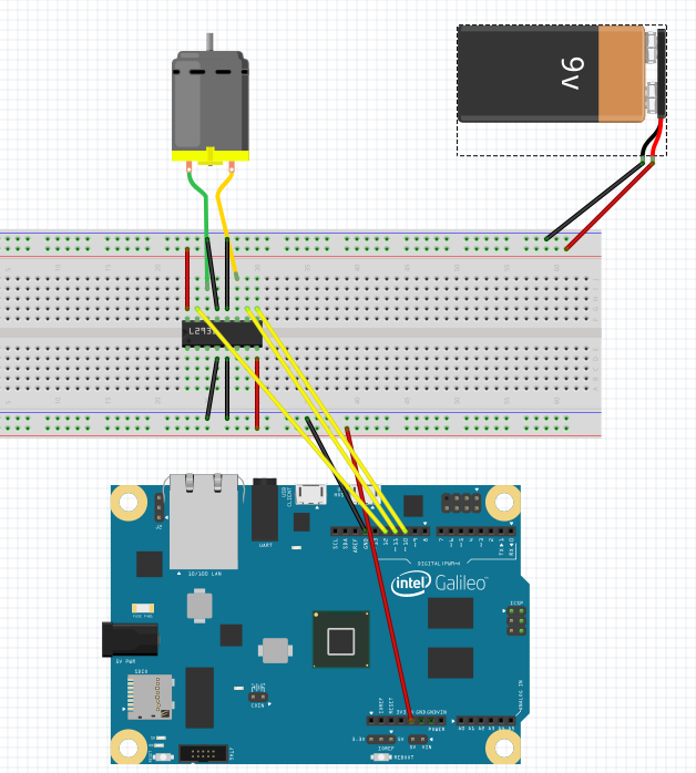
I decided to use there 5V power from my board in order to set up VCC1 because recommended voltage for VCC1 is between 4.5V and 7V. But you may use external power there as well, using some resistors there. In order to set up VCC2 I decided to use 9V battery, because my DC motor operates find under this condition. Finally, we should understand, how to operate the motor. In order to do it, you can use the following table:
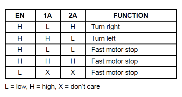
So, if you want to start the motor, you may use the following code:
  pinMode(en, OUTPUT);
 pinMode(a1, OUTPUT);
 pinMode(a2, OUTPUT);

 digitalWrite(en, HIGH);
 digitalWrite(a2, HIGH);
 digitalWrite(a1, LOW);
There en, a1 and a2 are numbers of digital pins, which you use in your Galileo in order to communicate with chip.
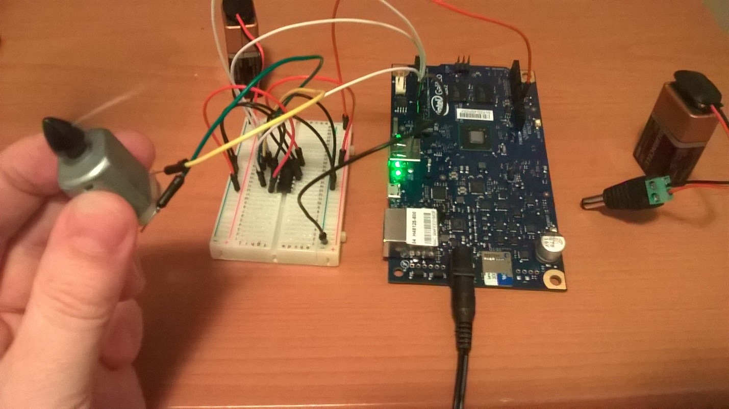
Finally, I got a working solution: