Internet of Things: My first experience with Galileo 2 (part 4)
Today I am going to continue my series about Galileo 2 board for beginners and I will discuss analog inputs. But before it, I want to discuss resistors as well.
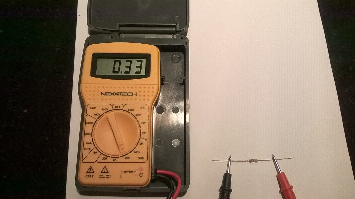
We already used several resistors in our projects in previous posts but it’s still too hard to understand a value of particular resistor. There are two ways to do it. First of all we may use a multimeter device. You can buy it in any electronics shop. If you want to find a resistor in 330 ohm you need to set the dial of multimeter to 20 KOhm and touch red and black probes of multimeter to different legs of the resistor. You will see something around 0.330 for 330 ohm resistor.
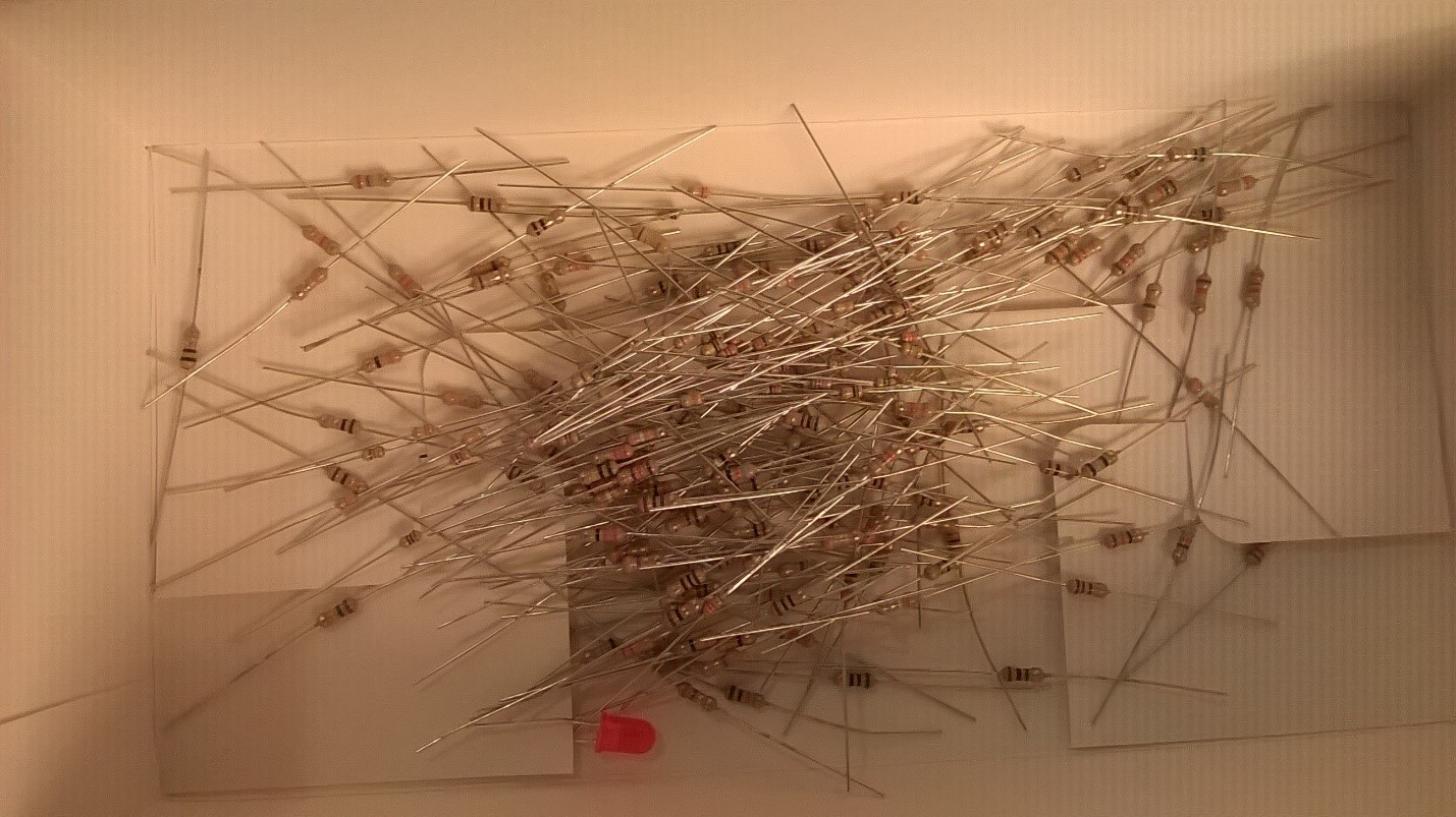
At the same time it’s not easy to find a right resistor among many types of them. Here is my box with different types of resistors and there are about 4 resistors in 330 Ohm only. Probably I will spend up to one hour in order to check all of them.
So, in order to find a right resistor you need to use the second way – you need to understand color marks there. It’s not too hard. Usually, you will find resistors with 4 or 5 bands there. Based on these bands you can calculate resistance of a particular resistor. Here is a small table, which will help:
Color |
1st Band |
2nd Band |
3rd Band |
Multiplier |
Tolerance |
Black |
0 |
0 |
0 |
1 Ohm |
|
Brown |
1 |
1 |
1 |
10 Ohm |
1% |
Red |
2 |
2 |
2 |
100 Ohm |
2% |
Orange |
3 |
3 |
3 |
1 KOhm |
|
Yellow |
4 |
4 |
4 |
10 KOhm |
|
Green |
5 |
5 |
5 |
100 KOhm |
0.5% |
Blue |
6 |
6 |
6 |
1 MOhm |
0.25% |
Violet |
7 |
7 |
7 |
10 MOhm |
0.10% |
Grey |
8 |
8 |
8 |
|
0.05% |
White |
9 |
9 |
9 |
|
|
Gold |
|
|
|
0.1 |
5% |
Silver |
|
|
|
0.01 |
10% |
So, if you have resistor with 4 bands, you will not use 3rd band column. Just find the right number for the first band and the right number for the second band and combine them to the one number like <first number><second number>. And multiply this number by multiplier in order to get the final resistance. That’s why we need <Orange, Orange, Brown> forth band resistor in order to get 330 Ohm resistor.
Let’s start to create a project based on sensors, which can send inputs to our board. I wanted to use a flame sensor in the first project but today I woke up at 4 A. M. due to fire alarm in my building. Probably somebody forgot to turn off a stove or something like it but buzzer’s sound was terrible and I decided that it was a sign to stop my experiments with flame. So, we will use a photoresistor sensor.
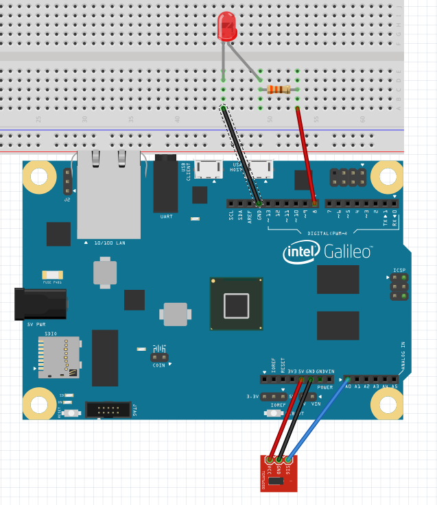
If you have a modern car, you should have something like “Auto” mode for your lights. This mode allows to switch your light based on amount of external light. We will try to emulate the same behavior in our project. In order to do it we will create a circuit like this:
Depending on your kit, you will find many types of photoresistors there. In my case I have an analog sensor, which looks like as a separate board:
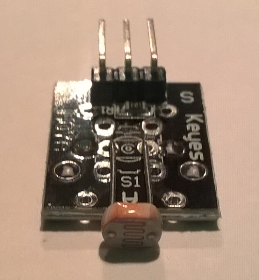
It has three legs, which should connect your sensor to power, ground and analog input pin on the board. You should check the datasheet for your sensor in order to understand how to connect it.
Since we are using an analog sensor, it should be connected to an analog pin. Photoresistor works like a variable resistor, which resists our voltage based on the amount of light. If you have a lot of light, the resistor will put down your voltage. Galileo converts the analog input to digital and it helps to understand the quantity of light. Here is a simple code, which you may use to test the project:
 int led = 8;
int photo = A0;

void setup()
{
 pinMode(led, OUTPUT);
 pinMode(photo, INPUT);
}

void loop()
{
 int res=analogRead(photo);
 if (res <= 700)
 {
 digitalWrite(led, LOW);
 }
 else
 {
 digitalWrite(led, HIGH);
 }
 delay(1000);
}
Galileo convertor will convert the analog input to a number between 0 and 1023. In this code I decided that if our number is smaller than 700 (resistor resists enough voltage), we will switch off our led because we have enough amount of light. If our resistor doesn’t resist enough voltage (it’s dark) we will switch on out led. Based on this example you are able to make many experiments with light and analog input.
Since we are using Visual Studio, it’s easy to launch our projects in a debug mode. When you will stop debugging, Visual Studio kills your process automatically. Visual Studio allows us to set breakpoints and review variables values etc. You may also use the Log method in order to print something to the output screen in the Debug mode. If you are launching your application without Debug mode, you need to kill your process using the Telnet as I mentioned in previous articles.
So, Visual Studio makes our life better but there still is a question: how to launch our projects just after startup of our operation system. It’s very important if you already created the final version of your project. Because we are using Windows, it’s easy to do in two steps. First of all you need to navigate to the following folder: \\mygalileo\c$\Windows\System32\Boot. You will need to enter your credentials there. On the next step, change autorun.cmd file and put one more command there, like start YourFolder\YourApp.exe. That’s all and your application will launch on the system startup.
Today I will finish my post. Next time I am planning to show more advanced projects.