Internet of Things: My first experience with Galileo 2 (part 2)
In the previous article we discussed how to setup your first Galileo board and showed some stuff that you need to deploy applications there. In this article we will try to understand what is Galileo and how we may use it in more advanced projects.
So, Galileo is a powerful development platform with x86 compatible processor, USB, mini-PCI, Ethernet port, 256MB DDR3, SD slot, which may help makers, students and enthusiasts to develop their own projects. Galileo is compatible with Arduino prototyping boards, so developers may use any existing hardware, which could be used with Arduino Uno or something like this. And, of course, Galileo may support not just Linux but Windows platform as well. It allows us to create our software in a friendly environment.
Of course, Galileo is the heart of your device and enables reading some inputs from external world and provides own outputs there. For example in order to get inputs you can use many different sensors, buttons, switches etc. and in order to show some outputs you can use motors, LEDs, relays etc. Thanks to the Ethernet adapter, 3G and WiFi shields, Galileo may communicate with external services and other devices, which are connected to Internet.
Our goal, in this article, is to understand how we may connect external devices to Galileo and how we may start developing something. From this prospective we will start with the most important part of the board for developers – with pins. Galileo 2 contains two sets of pins, which allow us to control inputs and outputs. In every project we are going to work with pins, that’s why their understanding is so important.
Usually we will work with the first set of pins – Digital pins. We may use this set in order to send outputs and receive inputs. You can use these pins for outputs in on/off mode. So, output voltage may have 0V or 5V there. Pay attention that all pins provide 5V voltage but Galileo board has a special switcher, which allows to set board in 3.3V mode in order to guarantee compatibility with some 3.3V shields. We will use just 5V voltage in our devices. If you use this set of pins for inputs, you will have the same range of values there – 0V or 5V.
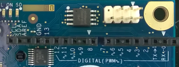
So, we have 13 pins for digital outputs/inputs. But you can notice that some of these pins have a special mark “~”. This shows that we may use marked pins in order to send signals (outputs) in pulse mode. It allows us to emulate rheostat effect, when we have a way to send just n% of current per unit of time. You can use this effect in order to regulate brightness of LEDs or temperature in your apartment etc.
The second set of pins (A0-A5) is used for input only. But in this case it should be analogue input like data from thermometers, potentiometers, variable resistors etc.
This set of pins is important then we receive data, which describes more than two states. We will use these pins in more advantage projects.
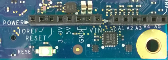
Finally you can find some more pins like POWER, 5V, GND and so on. Some of these pins are used in order to control the board, some pins like 5V and VIN are used as source of current and GND pins are used for the ground.
So, right now we got some knowledge about pins and it’s time to look at development tools for Galileo.
If you already installed VS Extensions for Galileo, you can create projects in C++ based on Galileo Wiring App template. Frankly speaking, Microsoft already included much code there but it allows us to concentrate on device only. Right now we can work with Main.cpp files only. Probably, later, we will dig to code there but today I am going to use already prepared stuff. So, there is the following code in the main.cpp file:
#include "stdafx.h" #include "arduino.h" int _tmain(int argc, _TCHAR* argv[]) { return RunArduinoSketch(); } int led = 13; void setup() { pinMode(led, OUTPUT); } void loop() { digitalWrite(led, LOW); Log(L"LED OFF\n"); delay(1000); digitalWrite(led, HIGH); Log(L"LED ON\n"); delay(1000); }
There are three functions only. Of course the application will begin with _tmain, which runs RunArduinoSketch functions. The main task of this function is calling setup function and putting loop function inside infinity loop. So, it’s clear that we can use setup function in order to initialize something there and we will use loop function in order to create our runtime logic.
We can see that setup and loop functions are already prepopulated. There is just one call from setup function – pinMode method, which informs our board that we will work with pin number 13. This pin is also connected to a led on the board but we can still use it for external stuff. loop method contains just six lines of code but the most important call there is digitalWrite call. This function allows two parameters like number of pin and state. LOW state shows that we should have 0V voltage and HIGH – 5V.
Let’s use existing code in the template but we will try to use external LED there. In order to do it we need the following components:
- LED – usually LED consumes voltage around 1.7V. So we should resist our 5V voltage there and in order to do it we need a resistor;
- Resistor – in order to resist our voltage we need 330 ohm resistor. It’s time to remember high school and Ohm’s low: I=U/R, where I is current (amperage), U is voltage and R is resistance. So, Galileo board has current in 10 milliamperes and voltage in 5V but we need to select a resistor, which will resist voltage to 1.7V: (5-1.7)/0.01=330. I used a resistor, which contains rings in the following sequence: orange, orange, brown and gold colors. In the next article I will describe how to select the right resistor;
- Breadboard – usually you will use this stuff in order to create a prototype of your final board and it’s good for testing and investigations. You can buy this one separately or find it in many kits;
- 2 wires
Finally, I created this:
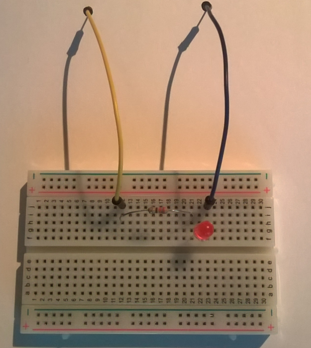
In order to understand how it works, you need some information about the breadboard. You can see that our breadboard has several lines that are marked by numbers (from 1 to 30). Pins in each of these lines are connected. So, I used a yellow wire in order to connect pin on my board to pins in line 12 on my breadboard. So, when I put my digital pin to HIGH, current will be in line 12. The resistor connects line 12 and 21, so, we will have 1.7V voltage in line 21. It’s time to connect our LED – put the longer lead (anode) to the same line (21) and put the shorter lead (cathode) to line 23. To the same line (23) connect the blue wire.
Next time I will try to create some schemas but many developers (like me) don’t have knowledge in electrical schemas at all:)
Finally, you can connect yellow wire to digital pin 13 and blue wire to GND pin and just deploy the default application from Visual Studio. Your led should blink. In order to stop the process you can use telnet and tlist/kill commands there.
In the next article we will test more sensors and functions from API.