The UML Model Explorer
In the VSTS 2010 Architecture product, we've added another toolwindow to VS designed to help you understand and manipulate the UML models that you will be building. The UML Model Explorer ( that's what we're currently calling it, but that can certainly change :) ) is a WPF component that represents the UML Package hierarchy of your models. "Models" in this context refer to the contents of the Modeling projects you have created and added to the current solution. The root node or nodes of the UML Model Explorer are UML packages representing those Modeling Projects.
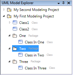
For example, in the image below, I have created two Modeling Projects, "My First Modeling Project" and "My Second Modeling Project". You'll notice that the UML Model Explorer has two corresponding nodes in the tree.
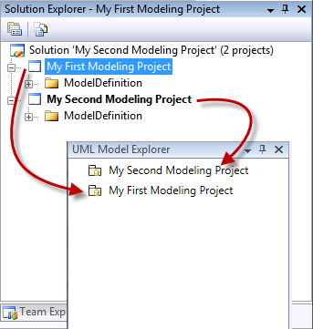
You might immediately be asking yourself "What's up here? Why show this same information in two tree controls?" The reason will become more clear as I continue on, but it is worth pointing out right now that the UML Model Explorer is a "logical" view over you models. The Solution Explorer is showing you the "physical" view of how those models are contained and persisted. Keep that in mind as you read on.
As I mentioned earlier, every time you create a Modeling Project, a new node will be displayed in the UML Model Explorer. That node is actually a UML package named after the Modeling Project, and serves as the root package for all modeling elements that will be serialized into the Modeling Project. Creating a Modeling Project is the only way to create a root node in the UML Model Explorer.
In the VSTS 2010 CTP, any and every element created under one of these roots is stored in the ModelDefinition.uml file found the Modeling project. In the current bits, we actually create a .uml file for every UML package created. When you intially create a Modeling Project, the UML Package that represents that project is persisted on disk in the ModelDefinition.uml file you see in the project. Every model element created in that package, except new Packages, will be stored in that same file. if you create a new Package, an additional .uml file will be created to store the data behind that package, and all its contents.
Let me drive this all home with some examples, and at the same time show some of the additional capabilities of the UML Model Explorer.
Adding Elements
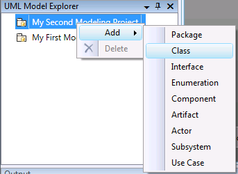
I want to add a class to the "My Second Modeling Project" model. I can do that by right-clicking on that node in the UML Model Explorer, and select Add->Class.
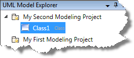
Each time I do that, a new class will appear underneath the "My Second Modeling Project" node.
To name the class, I hover over the current name, double-click, which allows me to rename the element. ( By the time we RTM, upon adding the new class, the tool will automatically put you in rename mode, as 99% of the time, that's what you will most likely be doing after adding an element in this manner. )
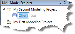
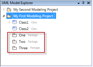
Below is an image of the explorer after adding a few elements. Notice, in small light-grey text is a label that indicates what type of element the node represents.
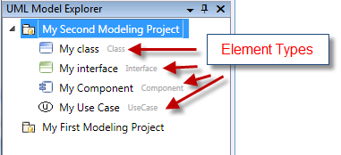
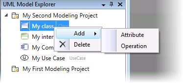
The types of elements that can be added depend on the node you right click on. So far, I've been right-clicking on the Package node that represents the root of my model. If I right click on the class or interface element, I can add UML Attributes or Operations as well.
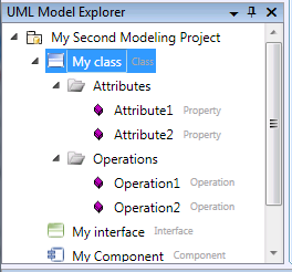
Here's what the explorer looks like after adding a couple Operations and Attributes:
Adding elements directly to the UML Model Explorer is great, but that is not the only way to add elements of course. As you drop new elements on diagrams, you will see those elements represented as you would expect.
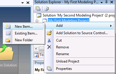
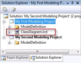
For example, I'm going to create a new Logical Class Diagram in the "My First Modeling Project" project by right clicking on that project node in the Solution Explorer, selecting Add->New Item..., which brings up the "Add New item dialog", where I select "Logical Class Diagram", give it a name, and hit "OK".
I now have a blank class diagram in the document well, and my project has a new file inserted into it:
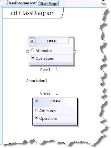
Now I drop two classes on that diagram and create a UML Association between them. Like so:
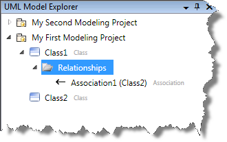
Now over in the UML Model Explorer, you'll see the two new classes underneath the "My First Modeling Project" node. You'll also notice the Association relationship also being represented:
But how did the tool know to create those new elements underneath the "My First Modeling Project" when dropping them on the diagram we just created?
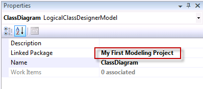
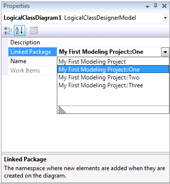
By default, whenever creating any type of UML diagram in a Modeling Project, that diagram's "Linked Package" property is set to the UML package associated with the project itself. That property is used when dropping new elements to figure out what UML package the new elements should be directly contained by. So in this example, that property is set to "My First Modeling Project", as seen below:
Let's drive this home with a more complicated example, and point out a couple more features of the system while we're at it.
First, I'm going to create three new UML Packages underneath the "My First Modeling Project" node, the results shown below:
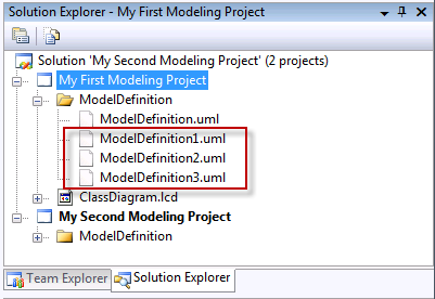
Now remember when I mentioned that creating a new package would result in a new .uml file being added to the Modeling Project? Take a look at the Solution Explorer, and the "My First Modeling Project" node. You'll notice three new .uml files added to that project, one for each new package I added ( again, the first uml file was already there ):
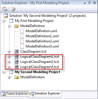
Now I'm going to create three new class diagrams and associate them with the newly created packages. I do that by right clicking on the "My First Modeling Project" project node in the Solution Explorer, select "Add->New item...", select "Logical Class Diagram", and hit "OK" three times. Here's what my Solution Explorer looks like when done ( red square pointing out the new diagram files added to the project ):
I associate "LogicalClassdiagram1" to the "One" package my setting that diagram's "Linked Package" property appropriately:
I do the same thing for the rest of the diagrams, pointing "LogicalClassdiagram2" to the "Two" package, and "LogicalClassdiagram3" to the "Three" package.
Now I drop a new class onto each of the new diagrams. The UML Model Explorer looks like this:
Paste By Reference and Element Delete
One of the great things that the UML Model Explorer makes very easy is the ability to represent the same model element on numerous diagrams, simply by dragging the element from the explorer onto the diagram. Let me show you what I mean.
I am going to drag "Class1" onto the three class diagrams I just finished creating. Here's the result:
Class1 is now represented on all three diagrams.
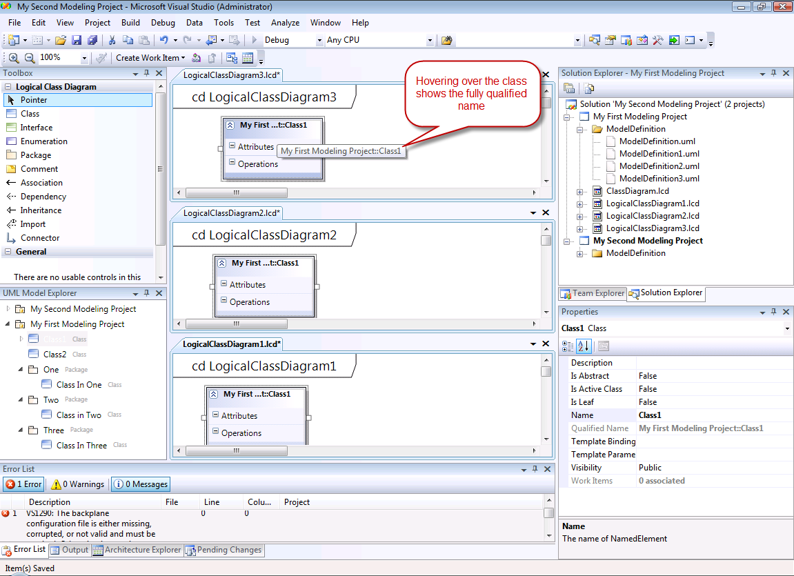
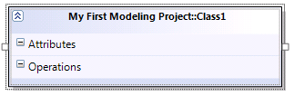
NOTE You'll notice in the image above that Class1 is represented on the diagrams with an elided name. Hovering over the element will show the fully qualified name. You can also widen the element to see the full name:
The reason for this is due to the fact that the diagram this shape is being displayed does not represent the same package that the model element is in. In this case, the LogicalClassDiagram3 represents the "Three" package, not the "My First Modeling Project" package which Class1 is directly owned by. |
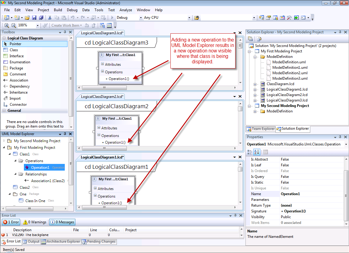
There is still only one "Class1" element in the UML Model Explorer. If I add an operation to Class1 via the UML Model Explorer, that operation will immediately be displayed in the Class1 on each diagram. This is because the shapes on each of those diagrams is essentially a view into the model data that is Class1. Changing the Class1 model data, which is exactly what changing that data in the Model Explorer does, results in the views of that data also changing.
And of course, adding a new Attribute to any of the Class1 shapes ( also called "Presentation Elements" ) results in the Class1 model data being updated, which updates all the other shapes, and so on.
Dragging from the UML Model Explorer is the most straight forward way of creating "references" back to the model data, but so is copying a shape and selecting "Paste By Reference" in the context menu.
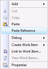
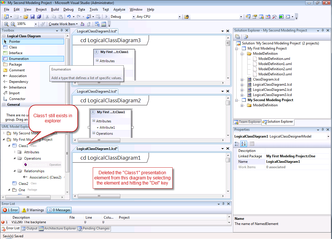
Now deleting one of the shapes results in the shape being deleted, *not* the model element itself. So if I delete Class1 from LogicalClassDiagram1, nothing happens except that shape is removed from that diagram. Class1 is still present in the UML Model Explorer.
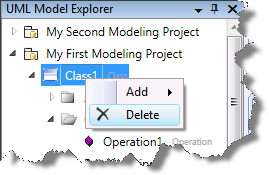
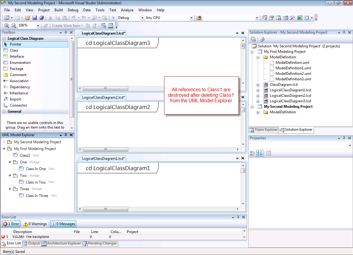
If I right click on Class1 and select "Delete", the model data is destroyed, along with all the shapes representing that element:
Summary
I hope that gives you a good taste of what the UML Model Explorer is all about. They key takeaway that I'm hoping you'll walk away with is that the UML Model Explorer is the logical view of the model repository contained by the Modeling Project. It represents data that can be displayed across numerous diagrams. That data can be manipulated directly via the explorer or through manipulation of presentation elements.
By the time we RTM, we hope to have a number of other facilities plugged into the UML Model Explorer, such as:
- Ability to represent Diagrams directly in the explorer
- Double click elements in the explorer will navigate to the diagram that element is represented on. If represented on many diagrams, you will be presented with a dialog allowing you to select which diagram to navigate to.
- Support for moving elements between packages inside the explorer
- Filtering of the explorer
As usual, would love to hear your feedback!