VSTS 2010 Architecture : [Part Two] Model Project and 4+1 Project Template
In my last post, I introduced the Modeling project that will be introduced in the VSTS 2010 Architecture product. In this post, I'd like to demonstrate how you can leverage the extensibility mechanisms inherent in the Visual Studio Project template feature set, and provide your organization with a template that can be used to pre-populate new modeling projects according to your specific problem domain.
The example I will demonstrate here is fairly simple, but complex enough to show the real possibilities.
( As you go through this post, keep in mind ideas of modeling templates that you think we should ship in the box at RTM time. I'd love to hear the ideas! )
| Process NoteThe VSTS 2010 CTP has been available since last month's PDC. What that essentially means is that the bits you see in the CTP were locked down late September. I have been wrestling with the following question: Should I limit my posts about the Architecture product to only the bits you see in that CTP, or show the current bits?I've decided to show the current bits and try as best I can to point out the differences.Ultimately, it is your feedback that I am looking for. One could argue that being able to try the current bits is the best way to get a good handle on the product and give more valuable feedback. No doubt about it. But I also don't want to waste your time taking time to tell me and the team of needs that we have already put into the product.At this point in time the current bits and CTP bits are close enough to make most of these discussions relevant and easily understood. At least, that's the assumption I'm working against.Let me know if you think otherwise. :) -- Cameron |
4+1 Views
A common way of structuring models that has enjoyed some success in the modeling space was introduced in 1995 by Phillipe Kruchten, called "The 4+1 View Model of Software Architecture."
I want to show how you can take the Modeling project and create a structure that is largely conformant to the 4+1 view concept, and then make that a project template that can be used by the rest of your organization.
The Final Result
If you follow the detailed steps below, here's what you'll have ( here's the final template zip file ):
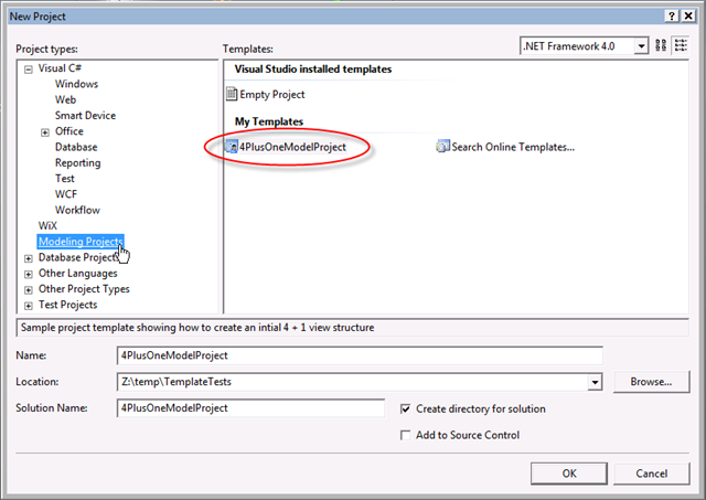
A new project template option seen in the "New Project..." dialog called "4PlusOneModelProject":
-
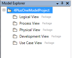
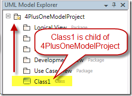
Once you've selected the "4PlusOneModelProject" and hit OK, you're Model Explorer will look like this:
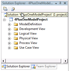
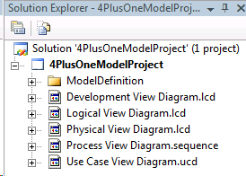
And your Solution Explorer will look like this:
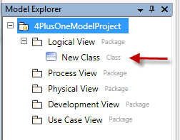
Now if you open one of the diagrams that was automatically created upon creation of the project, new elements added to the diagrams will be automatically associated with the proper package. For example, if you expand the "Logical View" node in the Solution explorer and double-click on the "Logical View Diagram.lcd" file, that will launch a UML class diagram. If you then drop a new class onto that surface, the new class will show up in the Model Explorer underneath the "Logical View" package node, like so:
The Details
Here are the steps I took to enable this functionality.
- Create the project structure using the existing template
- Export the template
- Modify the template
- Create code for ID replacement
- Deploy new template
Create the project structure using the existing template
The first thing we're going to do is create a new modeling project with the exact structure that we want to use as a template. Here we go:
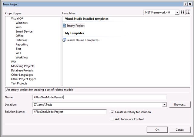
- Create a new Modeling Project. Here's a shot of my settings on the New Project dialog:
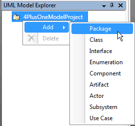
- Create the package structure as seen below by right-clicking over the "4PlusOneModelProject" root node in the Model Explorer, select Add, and choose "Package" for each of the five packages:
- Now we need to create diagrams that will represent each of the packages we just created.
- Let's create the "Logical View Diagram" first. We'll use a Logical Class Diagram for that.
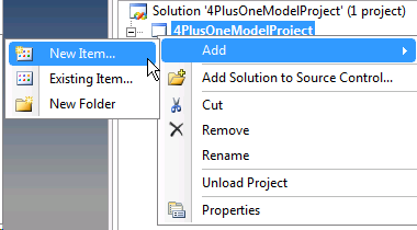
- Right click over the "4PlusOneModelProject" project node in the Solution Explorer and select "Add New Item..."
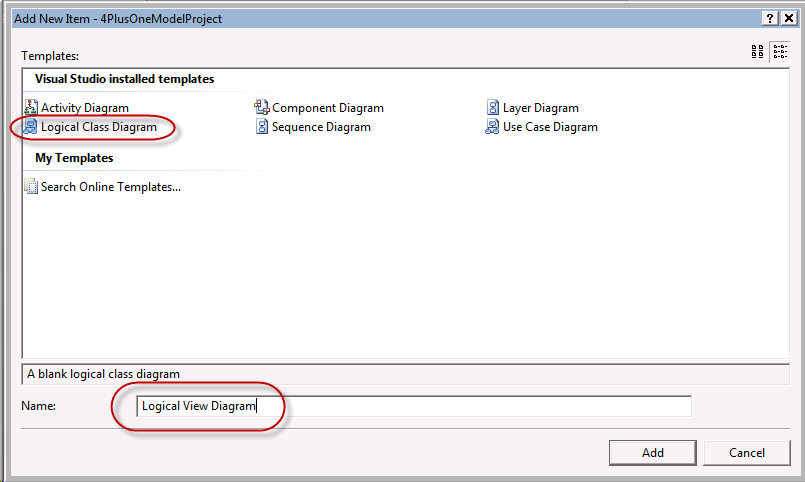
- In the "Add New Item - 4PlusOneModelProject" dialog, select "Logical Class Diagram", and give it the name "Logical View Diagram".
- Right click over the "4PlusOneModelProject" project node in the Solution Explorer and select "Add New Item..."
- Now let's create the diagram we want to associate with the "Process View"
- Right click again over the model project, select "Add New Item..."
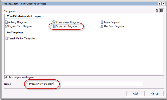
- In the "Add New Item - 4PlusOneModelProject" dialog, select the "Sequence Diagram" template, and name it "Process View Diagram"
- Ok, making progress! Three more diagrams to create! Follow the remaining steps to create the final three diagrams:
- Create a "Logical Class Diagram" called "Physical View Diagram"
- Create a "Logical Class Diagram" called "Development View Diagram"
- Create a "Use Case Diagram" called "Use Case View Diagram"
- When you're done with this section, your Solution Explorer should look like this:
- Let's create the "Logical View Diagram" first. We'll use a Logical Class Diagram for that.
- Excellent! Now we have all the diagrams and packages created, but we're not quite done creating the structure of this project. We now need to ensure that when ever one of your users creates an element say on the "Logical View Diagram", that that element is automatically made a child element of the "Logical View" package.
- Let's work with the "Development View Diagram" first.
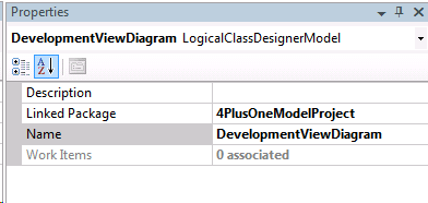
In the Solution Explorer, double-click on the "Development View Diagram.lcd" file. That will make the DevelopmentViewDiagram active in the document well. It will also make the "Properties" tool window display the properties of the diagram itself, as seen here:
You'll notice the "Linked Package" property, with a value of "4PlusOneModelProject". This property is telling the system "Hey, when anyone drops an element on this diagram, make that element a child of the 4PlusOneModelProject package." The 4PlusOneModelProject is the implicit UML package associated with the model project itself. Think of this as the "default namespace" for new elements.
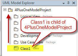
NOTE: The "Linked Package" property is *not* a property you will see in the CTP. This was added just after we locked the CTP bits. So if you drop a new class on the active diagram right now, you'll see that element show up at the root of the "Model Explorer":
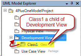
We want to change this default behavior so that the system says "Ok, whenever anyone drops an element on this diagram, make that element a child of the 'Development View' package." So we want this to happen upon when dropping a new class:
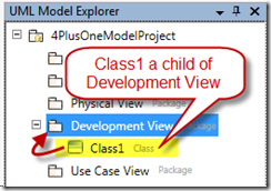
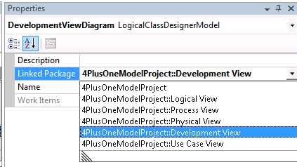
- Drop the list down for the "Linked Package" property, and select "4PlusOneModelProject::Development View"
- Now we need to set the appropriate "Linked Package" property on the rest of the diagrams.
- Double click on the "Logical View Diagram.lcd" file in the Solution Explorer and set its "Linked Package" property to "4PlusOneModelProject::Logical View".
- Double click on the "Physical View Diagram.lcd" file in the Solution Explorer and set its "Linked Package" property to "4PlusOneModelProject::Physical View".
- Double click on the "Process View Diagram.sequence" file in the Solution Explorer and set its "Linked Package" property to "4PlusOneModelProject::Process View".
- Double click on the "Use Case View Diagram.ucd" file in the Solution Explorer and set its "Linked Package" property to "4PlusOneModelProject::Use Case View".
- Let's work with the "Development View Diagram" first.
You might want to make sure that new elements dropped on each of the diagrams is properly rooted to the right package. Once you're satisfied that things are working the way they should, you're now ready to export this project structure!
Export the template
Now that we have the modeling project in the state that we want it, it is now time to export the structure of this project so that we can use it as a template.
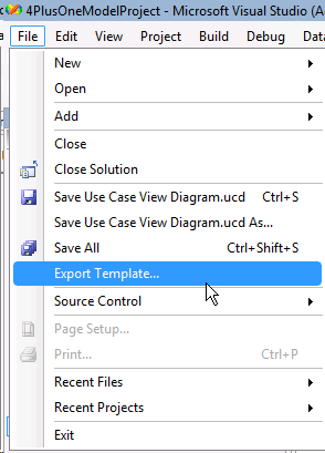
- Select "File->Export Template..."
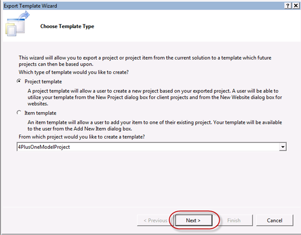
- You'll see the following dialog. Take all the defaults and press the Next button.
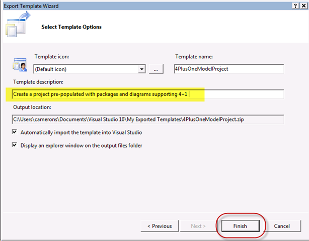
- On the next page, add an appropriate description for the new template. This is the description your users will see when selecting the template option in the "New Project..." dialog. Leave the other options in their default state. Hit Finish when done.
- Once you hit the Finish button, a new windows explorer will raise, showing you the folder where the new template file ( a zip file ) was created. Don't dismiss this window, as we need to modify the files in that zip file, which we'll do next.
Modify the template
At this point, the template coming out of the Export Template wizard could actually be used and deployed, but there are some subtle problems with this template that you should be aware of, all around the IDs used for the various model elements and diagrams. The system assumes that IDs for various model elements are universally unique, so GUIDs are used for IDs. If you took the template we just exported and started creating new modeling projects based on that template, the IDs for the elements we created ( e.g., the IDs for the packages ) would be the same for all new projects. We don't want to do this, so we need to modify the template in a way that causes new IDs to be created for all the elements in the project each and every time that template is used.
It turns out that the template functionality in Visual Studio supports this scenario for most normal situations. Check out this article that is still relevant today, and will continue to be in Visual Studio 2010. This article talks about the ability to support "Parameter Replacements" and lists a number of Built-in parameter replacements, one of which is support for GUID generation.
It might be tempting to simply go through the template, replacing like IDs with parameter replacement directives like "$guid1$" and "$guid2$". Problem is we have more than 10 IDs we need generated, so unfortunately, we can't use the built-in GUID parameter replacement mechanism. There is another way however, so all is not lost. ;)
We will create "CustomParameters" and write a very small amount of logic that we can associate with the project template. Let's create the CustomParameters now. We will create a CustomParameter for each unique ID found in the *.uml files in the ModelDefinition directory, as well as in all the various diagram files. ( The one noted exception to this is for the primitive types found in the ModelDefinition.uml file ).
This is by far the trickiest part of this exercise, as the IDs must be correctly placed in order to make everything work appropriately. Instead of walking you through each step, I've included the final template that you can take a look for yourself. Let me describe a few of the hilites however.
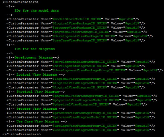
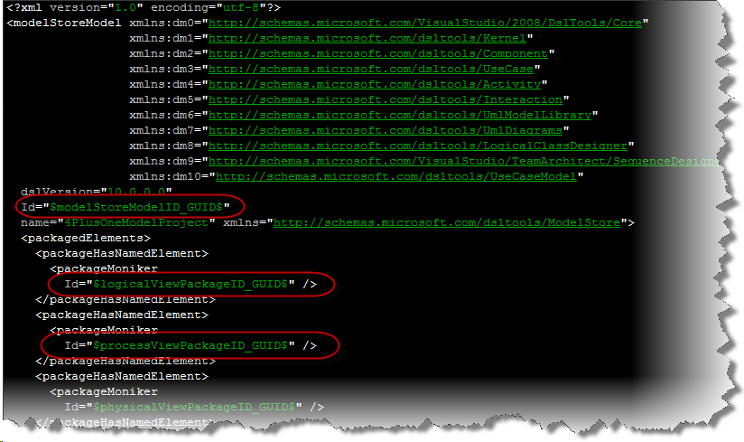
- In the "MyTemplate.vstemplate" file, you'll notice a CustomParameters section. This is where we setup the names of the parameters that we can use throughout the rest of the files in the project. You'll notice that all the names end with "_GUID$", which is important as I've got a bit of code that I'll show you in a second that handles the creation of the GUIDS for any parameter with that ending. The values of the CustomParameters does not matter.
- If you open the "ModelDefinition.uml" file in the ModelDefinition directory, you'll see some examples of those parameter names being used. You'll see something like this:
Create code for ID replacement
There is one last piece to this puzzle. I mentioned above of a small bit of logic necessary to handle the generation of the GUIDs. Here is another article that you can reference for more of the details on how to implement the IWizard interface. The steps are the following:
- Create a new C# Class Library project.
- Add references to EnvDTE and to Microsoft.VisualStudio.TemplateWizardInterface to your project references.
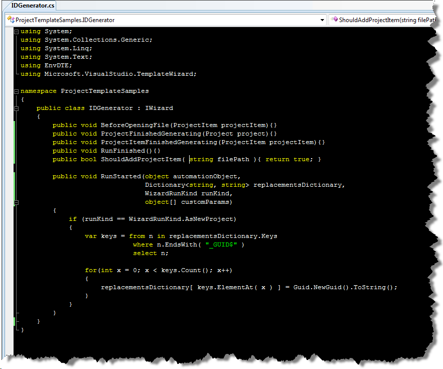
- Change the only .cs file in that project to contain the following code:
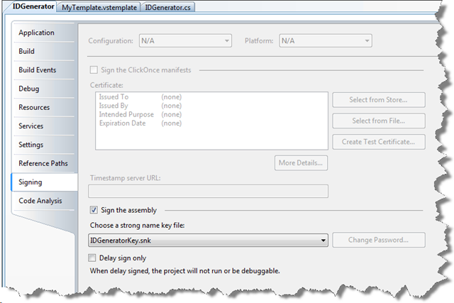
- Tell VS to sign the final class library assembly.
- Go into the project Properties by right clicking on your class library project and select Properties.
- Select the "Signing" tab along the left side of the properties editor.
- Check the "Sign the assembly" check box
- Drop down the combo box, select "<New...>", and give your key file a name.
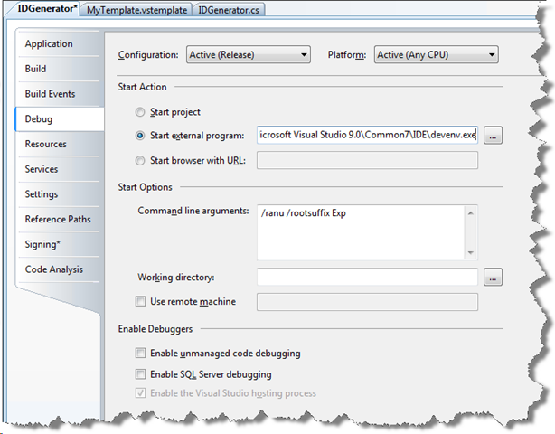
- For debugging purposes, click on the "Debug" tab, click the "Start external program", browse and find the "Devenv.exe", and set the following command line arguments:
- Add that assembly to the GAC
- Go to a command line and use the "gacutil /i <assembly name>".
- Add the following WizardExtension block to your MyTemplate.vstemplate file. Of course, you can't take exactly what I have here, as your PublicKeyToken will most certainly be different. You can get the exact text for your assembly by going to the command line and using "gacutil -l <name of assembly>":
-

Deploy new template
Deploying the new template is as simple as dragging the 4PlusOneModelProject.zip into the C:\Users\<USER NAME>\Documents\Visual Studio 2008\Templates\ProjectTemplates directory. You don't even need to restart Visual Studio to see the template when selecting "Modeling Projects" as seen in the "Final Results" section at the start of this post.
Summary
I've shown you how to create a project template that establishes a well-defined structure upon project creation. The simple idea here is to provide your organization a common starting point that is more specific to your organizations modeling needs. I've used the 4+1 structure as an example, but there are countless possibilities here.
What common templates should we include in the box by the time we ship the final version of product?