Windows 7 Sensor and Location API – Getting Started
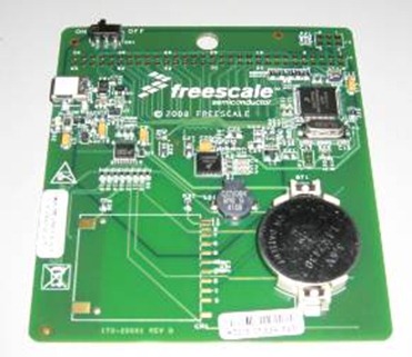
To get started working with the Sensor and Location API, you may want to purchase an inexpensive sensor board from Freescale called the Flexis JM Badge Board. For location you may want to purchase Streets and Trips (GPS) 2009 which includes a USB GPS device. These devices along with Visual Studio 2008 SP1 running on Windows 7 will give you a complete hardware/software prototyping development environment.
Note: you will want to order the JM Badge Rev-D version of the JM Badge board.
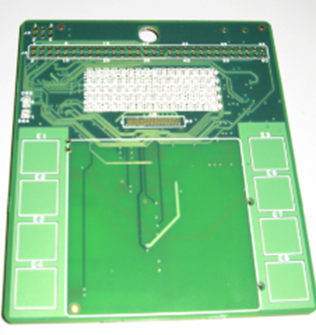
Back of Board |
Front of Board |
The board features these sensors:
- 3-axis Accelerometer
- Ambient Light Sensor
- Capacitive Touch Sensor (8 buttons split 4 left and 4 right)
The board has a USB adapter to connect it to your PC. Following the directions in the User Manual, make sure your board is functioning. There are a number of built in flashed demos for testing the board.
Next you will want to install the Windows 7 driver for the board and update the board’s firmware. The directions on how to do this can be found in the Sensor Developer Kit for Windows 7. (see the README file in the root folder)
Install the JM Badge Driver for Windows 7
- Navigate to the location of the files for the Sensor Development Kit for Windows 7
- Run SensorKitDriverInstaller.exe to install the drivers on your computer
- Connect the board to your computer by using the USB cable
- Install and run the sample applications that are included in the Sensor Development Kit
For more information about the sample applications, see the documentation that in the Sensor Development Kit files.
Updating the JM Badge board firmware
- Connect the board to the computer by using a USB cable. A message will appear on the LED display that says “Press E4 to enter bootloader.”
- Press the E4 button on the back side of the board.
- After you press the E4 button, a bar will appear on the LED display. The drive will mount on the computer, and the drive folder will open in a new window.
- After the bar on the LED display stops blinking, copy the .S19 file from the \Firmware\Binaries folder into the Sensor Developement Kit folder. The flashing of the drive will begin.
- When flashing is completed, a bar will appear on the LED display.
- Disconnect the board from the USB cable.
- Turn the board switch to ON. On the LED display, the message “Can your badge do this?” should appear. If this message doesn’t appear, you must redo steps 1 through 7.
- Turn the board switch to OFF.
- Connect the board to the computer by using the USB cable. After connecting the board, the LED display should display the message “bootloader.”
- After “bootloader” is no longer displayed on the LED display, the board should automatically be enabled for use with the Windows 7 sensor platform. If this message doesn’t appear, you must redo these steps 1 through 10.
In addition to the kit you will also want to download the samples and helper classes from the MSDN Sensor and Location API page:
Testing the Windows 7 / JM Badge Communication
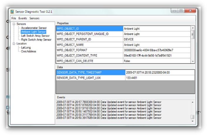
You can test that your board is working with Windows 7 by opening the Sensor Diagnostic Tool Visual Studio project. Build the project and run the application.
The application will connect to the board, enumerate the sensors and display the sensor properties and real time data coming from the sensor. This application is also a great code base for learning how to work with the .NET Framework class library that wraps the Sensor COM API.


