Application Lifecycle Management Part 3 of 5
Application Lifecycle Management Tools
This is the third blog on Application Lifecycle Management series. This part will mainly focus on the tools that span different development phases and how these integrate with each other to accelerate collaboration and improve time to market of your software product. For the past few days, I have been blogging about Application Lifecycle Management, you can read the previous posts:
Application Lifecycle Management Part 1 of 5
Application Lifecycle Management Part 2 of 5
Application Lifecycle Management - Part 4 of 5
Application Lifecycle Management Part 5 of 5
The Requirements Gathering Process
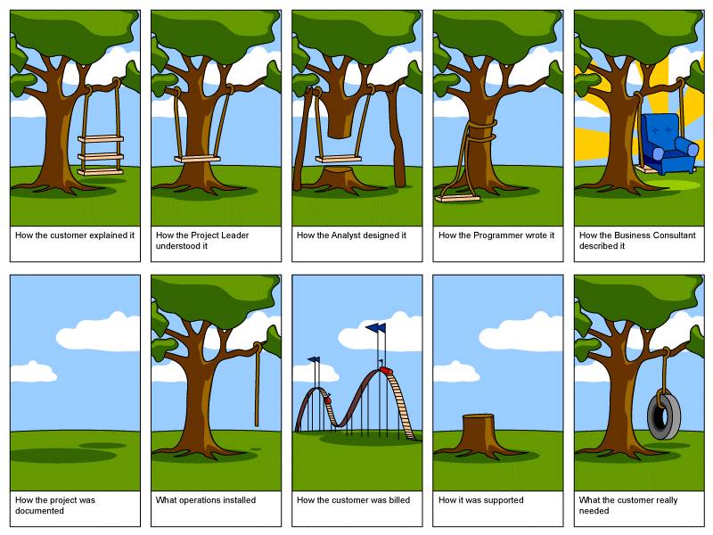
Requirements gathering is an essential part of any project, understanding fully what the customer requires may sound like common sense, but surprisingly it’s an area that is given far too little attention. The tree swing picture below demonstrates the dangers of departmental barriers, and
failures of departments to talk to each other, and to talk to customers.
One way of avoiding this problem is by producing a vision statement for your project. This can be achieved by having a brain storming session with the client and capturing the same within Visual Studio Ultimate as shown below.
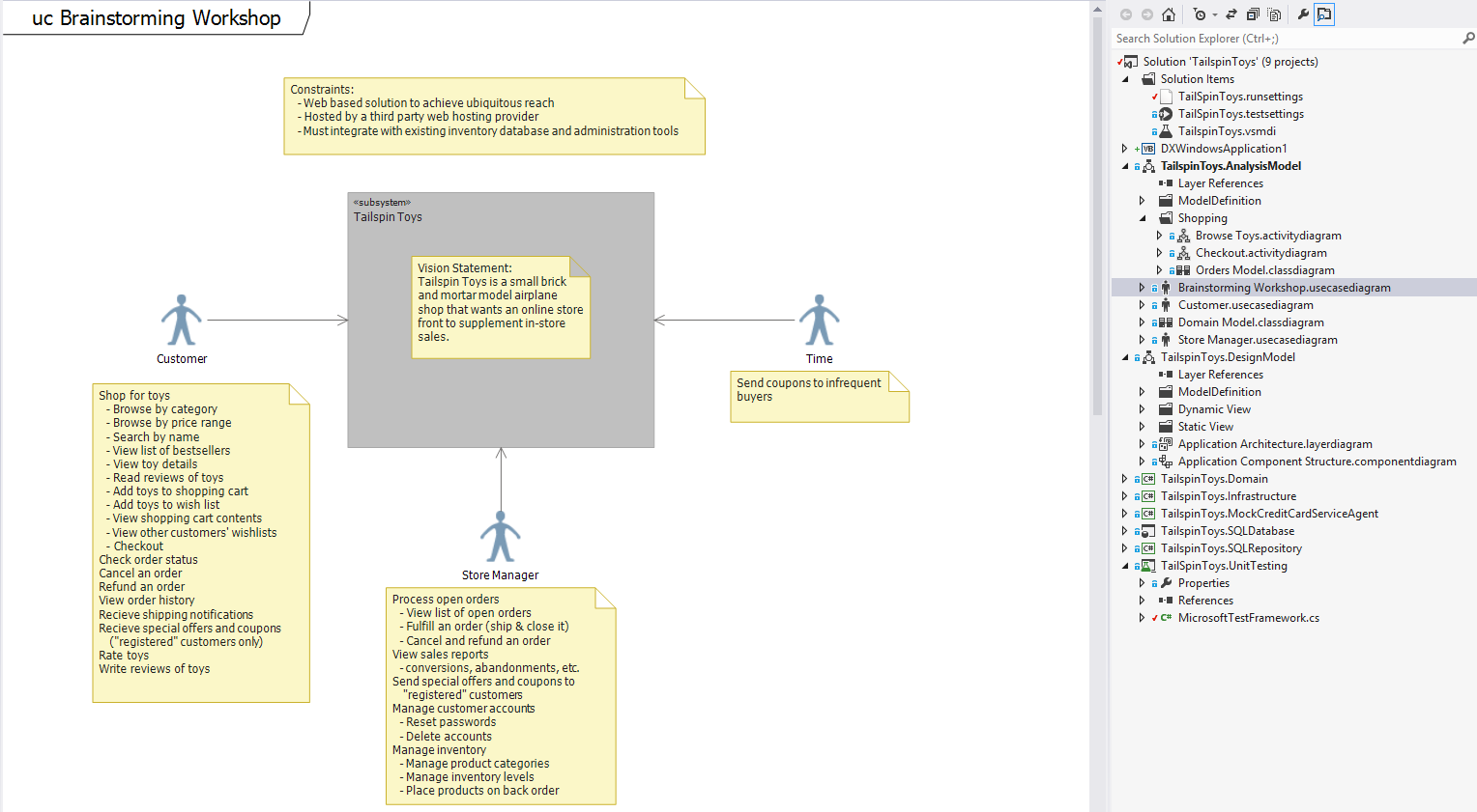
From figure above clearly shows that the brain storming session achieved the following.
- Defined the solution’s boundaries
- Identified who will be impacted by the solution
- Discovered what valuable activities will be automated
- Uncovered the constraints that will limit the solution
- Described goals from users’ point of view
Organize features into Use Case Models
Once we have captured the requirements from the user, we shall now breakup user goals and tasks into separate, digestible diagrams. A use case diagram represents a discrete unit of interaction between a user and the system. We shall use these diagrams as a structured writing requirements as use case diagrams. Here are a few tips when identifying use cases:
- Think of actors as roles, not job titles
- Use business domain terminology
- Focus on actor’s goals, not implementation details
- Use strong, active verbs in the names
- Focus on only one “feature area” in a single diagram
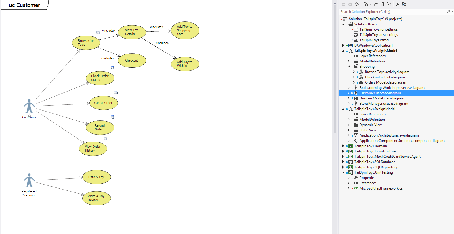
Customer use case diagram
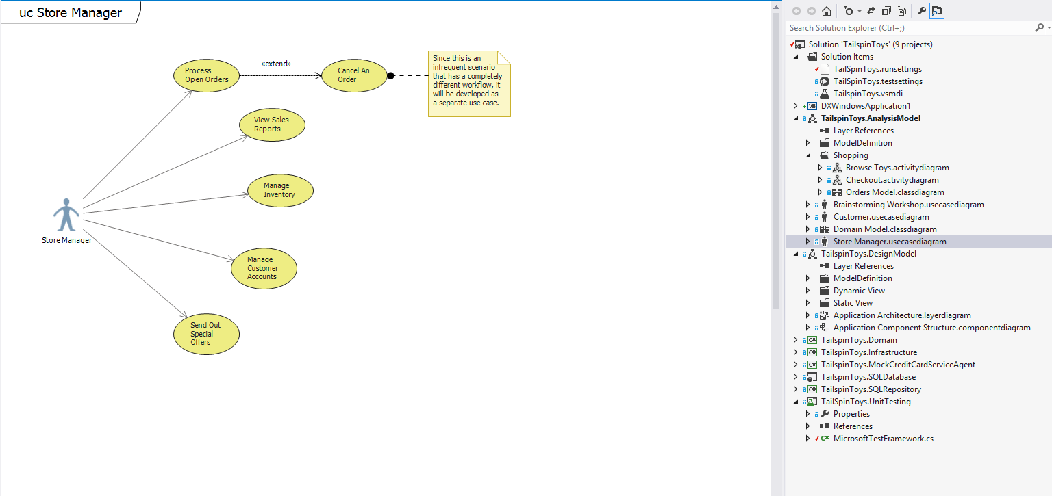
Store Manager use case diagram
Model the business domain using conceptual class diagrams
Class diagrams are fundamental to the modeling process of a system. They are useful in helping you understand the requirements of your problem domain and to identify its components. In an object-oriented software project, the class diagrams that you create during early stages of the project contain classes that often translate into actual software classes and objects when you write code. Later, you can refine your earlier analysis and conceptual models into class diagrams that show specific parts of your system, user interfaces, logical implementations, and so on. Here are some tips:
- Use friendly names
- Show just those classes needed in description of the requirements
- Focus on names and simple relationships
- Capture multiplicities to clarify the relationships
- Add attributes, and types only if they are needed to clarify a requirement
- Stay implementation-independent
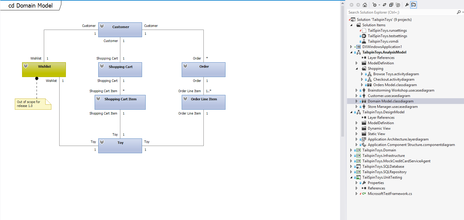
The domain model
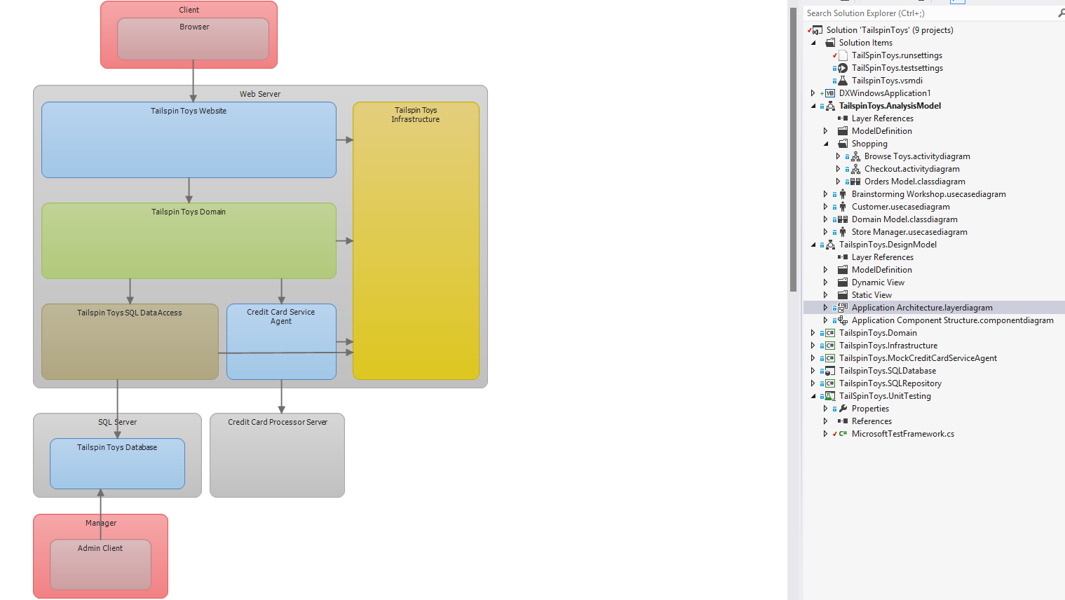
Architect the Application using a layer diagram
You can use a layer diagram to visualize the high-level, logical architecture of your system. A layer diagram organizes the physical artifacts in your system into logical, abstract groups called layers. These layers describe major tasks that the artifacts perform or the major components
of your system. Each layer can also contain nested layers that describe more detailed tasks.
You can specify the intended or existing dependencies between layers. There dependencies, which are represented as arrows, indicate which layers can use or currently use the functionality represented by other layers. By organizing your system into layers that describe distinct roles and
functions, a layer diagram can help make it easier for you to understand, reuse, and maintain your code.
Here are some tips:
- Minimize upfront design (avoid starting more than 1 namespace deep)
- Analyze and refactor at the beginning of each iteration
- Separate functional areas of concern cleanly
- Avoid duplicating responsibilities
- Minimize dependencies between layers
- Make it obvious where code needs to go
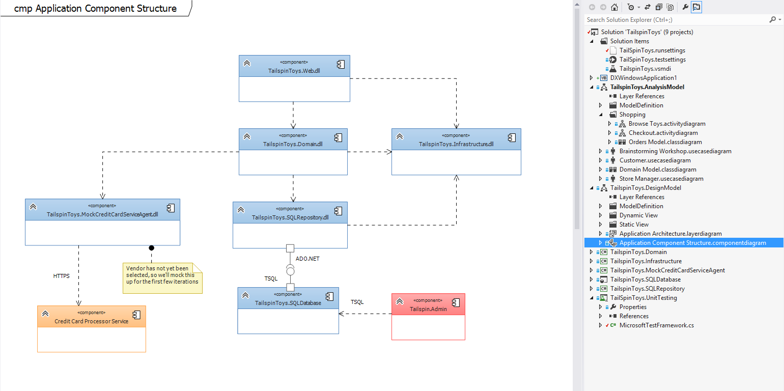
Design the Physical Structure using a Component Diagram
A component is a modular unit that is replaceable within its environment. Its internals are hidden, but it has one or more well defined provided interfaces through which its functions can be accessed. A component can also have required interfaces. A required interface defines what functions or services it requires from other components. By connecting the provided and required interfaces of several components, a larger component can be constructed. A complete software system can be understood as a component.
Drawing component diagrams has several benefits:
- Thinking of your design with regard to the major blocks helps the development team to understand an existing design and create a new one.
- By thinking of your system as a collection of components with well-defined provided and required interfaces, you improve the separation between the components. This in turn makes the design easier to understand and easier to change when requirements change.
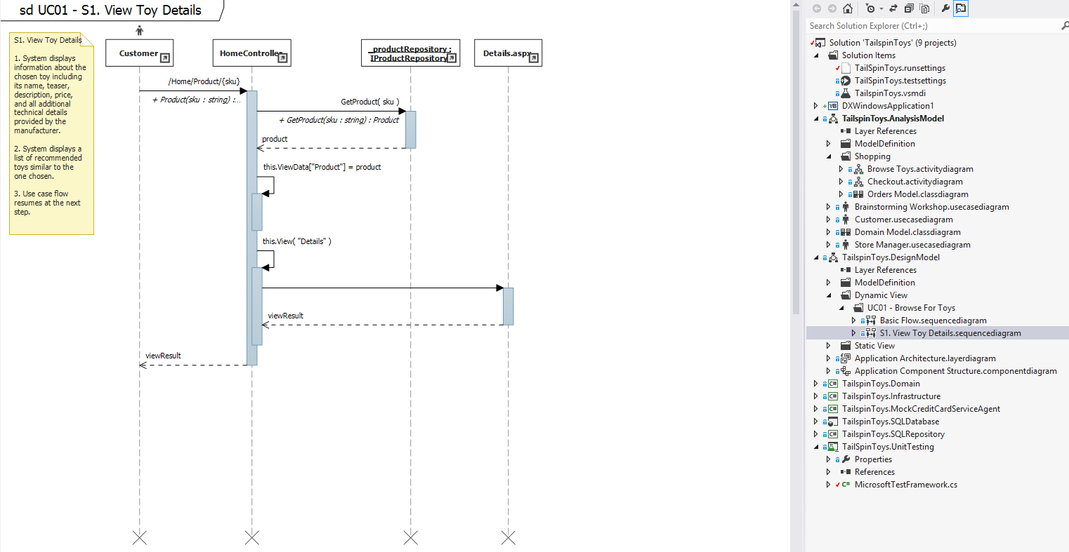
Sketch interactions with Sequence Diagrams
Sequence diagrams model the flow of logic within your system, enabling you both to document and validate your logic, and are commonly used for both analysis and design purposes. Sequence diagrams when combined with class diagrams and physical structure models are very important design-model for modern business application development.
Sequence diagrams are typically used to model:
- Usage scenarios - A usage scenario is a description of a potential way your system is used. The logic of a usage scenario may be part of a use case, perhaps an alternate course.
- The logic of methods - Sequence diagrams can be used to explore the logic of a complex operation, function or procedure.
- The logic of services - a service is effectively a high-level method, often one that can be invoked by a wide variety of clients.
We have discussed the process of requirements gathering and seen the various models that can be obtained as part of the development process. In summary the models we have discussed helps you to:
- Focus on the system’s external behavior, separately from its internal design.
- Describe the users’ and stakeholders’ needs with much less ambiguity than you can in natural language.
- Define a consistent glossary of terms that can be used by users, developers, and testers.
- Reduce gaps and inconsistencies in the requirements
- Reduce the work needed to respond to requirement changes
- Plan the order in which features will be developed
- Use the models as a basis for system tests, making clear relationship between the tests and the requirements. When the requirements change, this relationship helps you to update the tests correctly. This makes sure that the system meets the new requirements.
These models provides the greatest benefit if you use them to focus discussions with the users or stakeholders, and these can be revisited at the beginning of each iteration given that we shall be using the Agile Methodology of software development. Therefore, it is not necessary for you to complete each in detail before writing code, a partially working application, even if very much simplified, generally forms the most stimulating basis for discussion of the requirements with users.
References,
Use Case Modeling by Kurt Bittner and Ian Spence
UML 2 and the Unified Process by Jim Arlow and Ila Neustadt
Use Cases: Patterns and Blueprints by Gunnar Overgaard and Karin Palmkvist
References