Building a traffic signal with Christmas lights
It started out as a simple project. My children had become interested in basic electrical circuits so I bought them some LEDs, batteries, wire, and solderless breadboard to play around with. I soon found that these components weren't ideal for a number of reasons. While the solderless breadboard makes it easy to wire up circuits, it hides many of the electrical connections inside making it harder for children to grasp the concept of a circuit. In order to light up, the LEDs must be wired with the correct polarity and their uninsulated leads must not make a short. These factors combined to make it hard for the children to consistently build circuits that would light up.
A simple idea. I had a moment of inspiration one evening while walking my dog through the neighborhood in the days leading up to Christmas. I realized that miniature Christmas lights actually only require a few volts to light up. A string of Christmas lights runs on 120v, but the bulbs are wired in series so an individual bulb needs only 2-3 volts, a safe amount that can be obtained through a pair of flashlight batteries. (you can find out everything you ever wanted to know about Christmas lights here)
Christmas lights have a number of advantages over LEDs. They come in sockets with insulated wires already attached, they come in many colors, they all use the same voltage, and they don't care about polarity. Another benefit is cost. At most hardware stores you can purchase five replacement bulbs for about a dollar, but they don't come in sockets (see Figure 1).
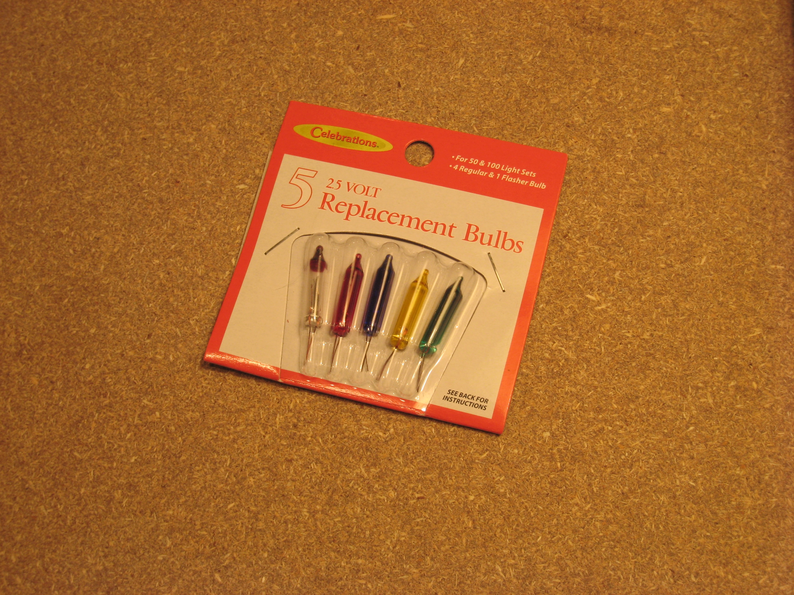
Figure 1. Five bulbs and no sockets for 99¢ at the local hardware store.
A better deal is to purchase 100 bulbs and 100 sockets and 100 feet of wire for about three dollars (see Figure 2) and if you wait until the day after Christmas you can probably do even better.
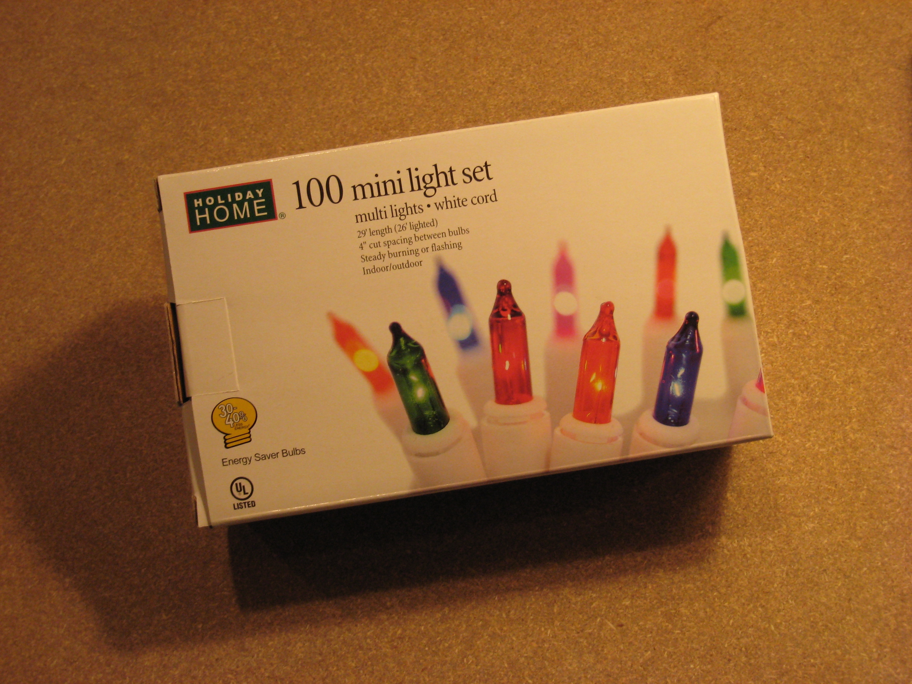
Figure 2. These bulbs cost about 3¢ each and come in convenient pre-wired sockets.
I ended up getting a few strings of lights along with a battery holder, some alligator clips, and a knife switch. After cutting a light out of the string I was able to make a simple circuit (see Figure 3) and I felt that it illustrated the concepts better than the LEDs and solderless breadboard. Everything in this circuit is visible and can be manipulated and arranged. I like how the knife switch really gets at the essence of closing a circuit.
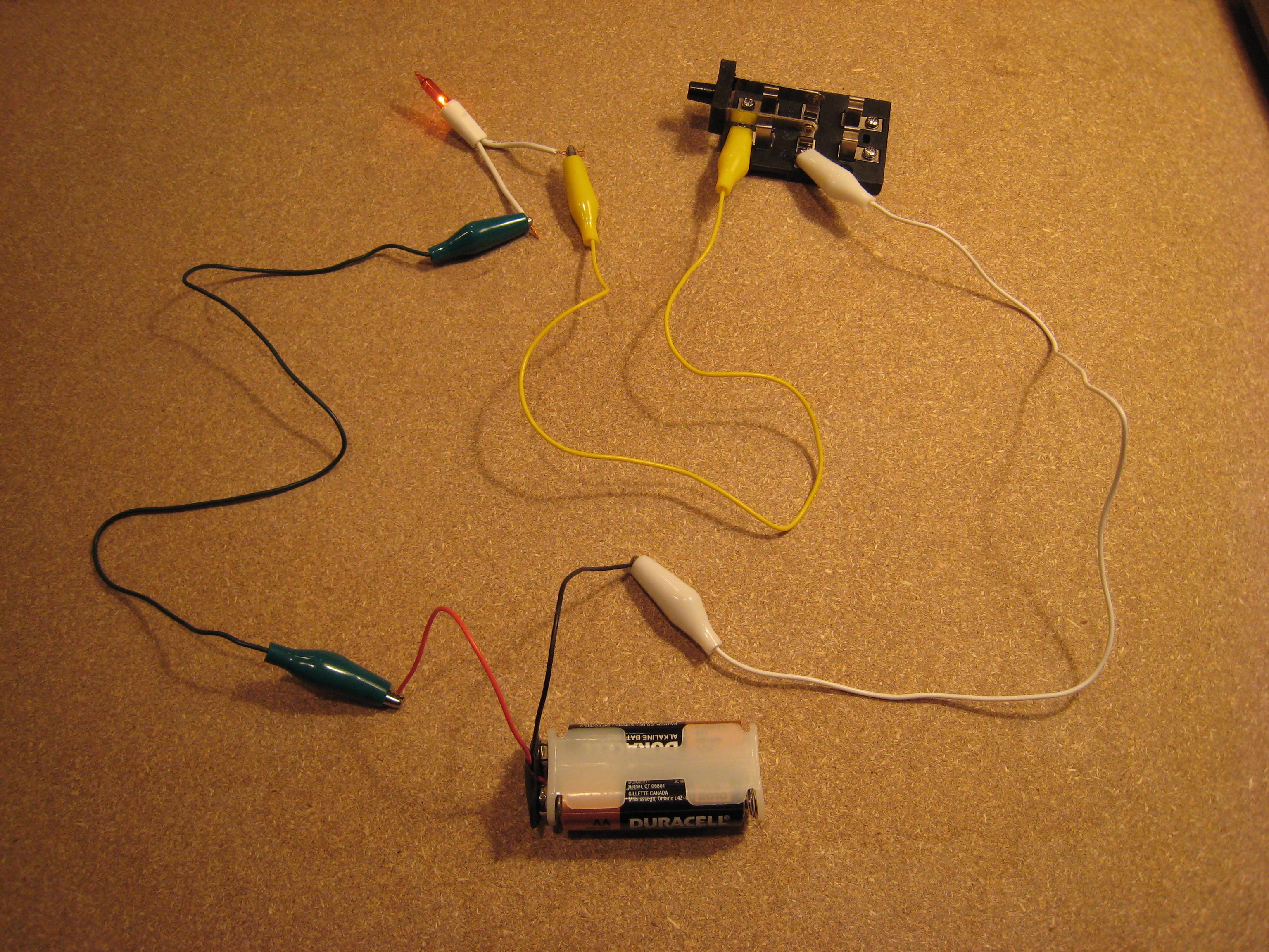
Figure 3. This circuit is easy to understand because everything is visible.
To be safe, I cut off both 120v plugs from the string of lights and then gave the lights to my kids along with a wire cutter/stripper and the batteries, alligator clamps, and knife switches. They quickly made simple circuits and then proceeded to wire up lights for their Lego creations and dioramas. I probably should have stopped here.
A simple idea grows into a bigger project. As I watched the kids play with the lights I got the idea to make them a stoplight. I knew it would be too complex for them to wire up by themselves, but I figured they could make a nice cardboard box for it and put it to good use. I decided to use a 2-pole 6-throw rotary switch from Radio Shack to control 12 lamps. This would allow green, yellow, and red lamps for roads coming from 4 directions. Before getting out the soldering iron, I wrote down the a simple state table for the 6 positions of the rotary switch (see table 1). After writing down the state table, I realized that a four-position switch would have worked better since the light cycles through four states before repeating. I only had a six-position switch so I went with the circuit in figure 4.
Table 1. State diagram for 2 roads crossing.
| Position | North/South Lamps | East/West Lamps |
| 1 | Green | Red |
| 2 | Yellow | Red |
| 3 | Red | Green |
| 4 | Red | Yellow |
| 5 | Green | Red |
| 6 | Yellow | Red |
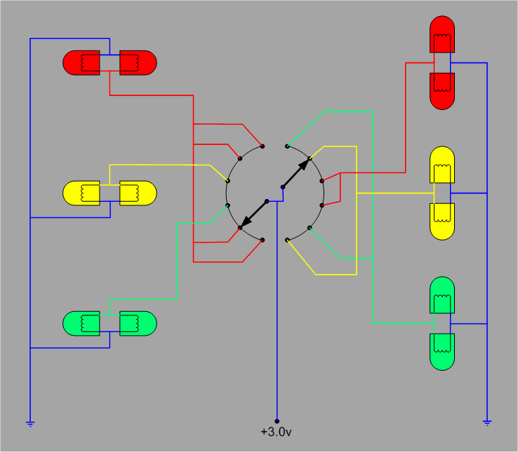
Figure 4. Circuit for 12 lights on a 6-position rotary switch.
The circuit looks pretty simple, but it actually took me a while to build. The time consuming parts were scavenging and testing 12 lamps (figure 5), and soldering in close quarters on the rotary switch (figure 6).
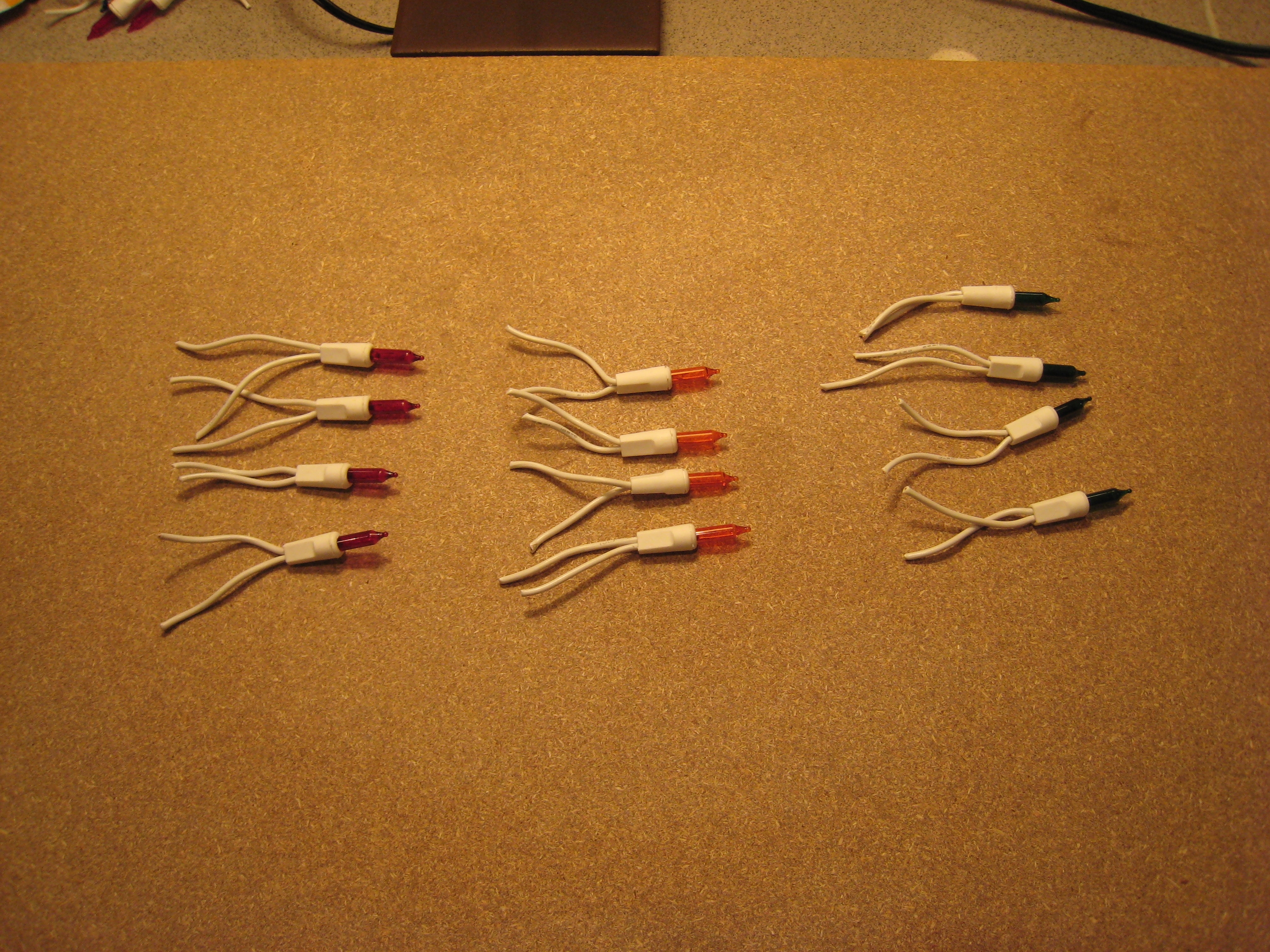
Figure 5. A stoplight seems pretty simple, but it actually has 12 lamps inside.
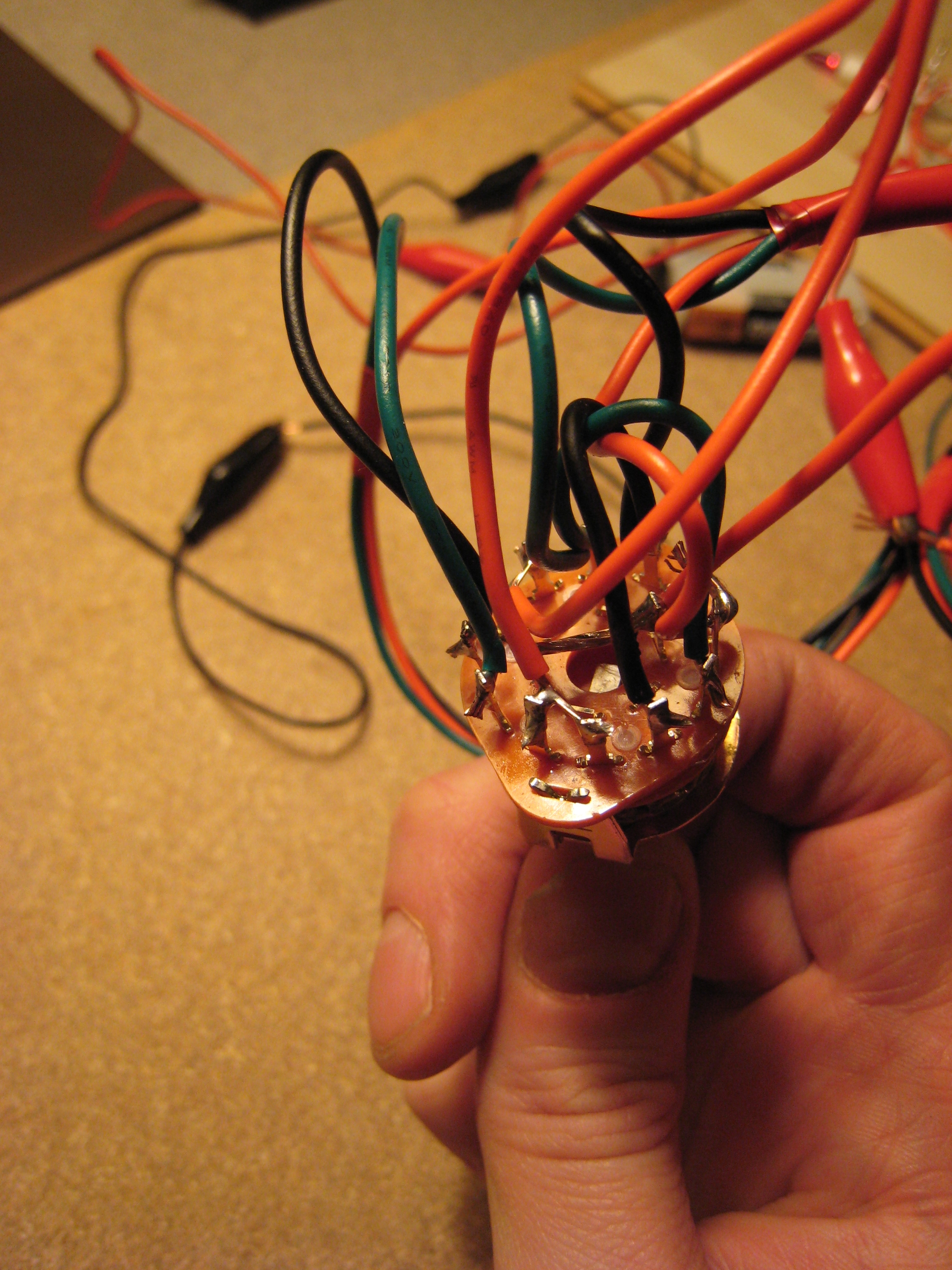
Figure 6. Wiring the rotary switch was tricky.
By the time I was done, I was really glad that I didn't attempt this project with the kids. They would have become bored long before the first solder melted. Figure 7 shows the completed circuit. I taped the bulbs to a board to help keep the wires under control and I made a long wire harness between the switch and the bulbs to simplify mounting in whatever enclosure the kids decide to invent.
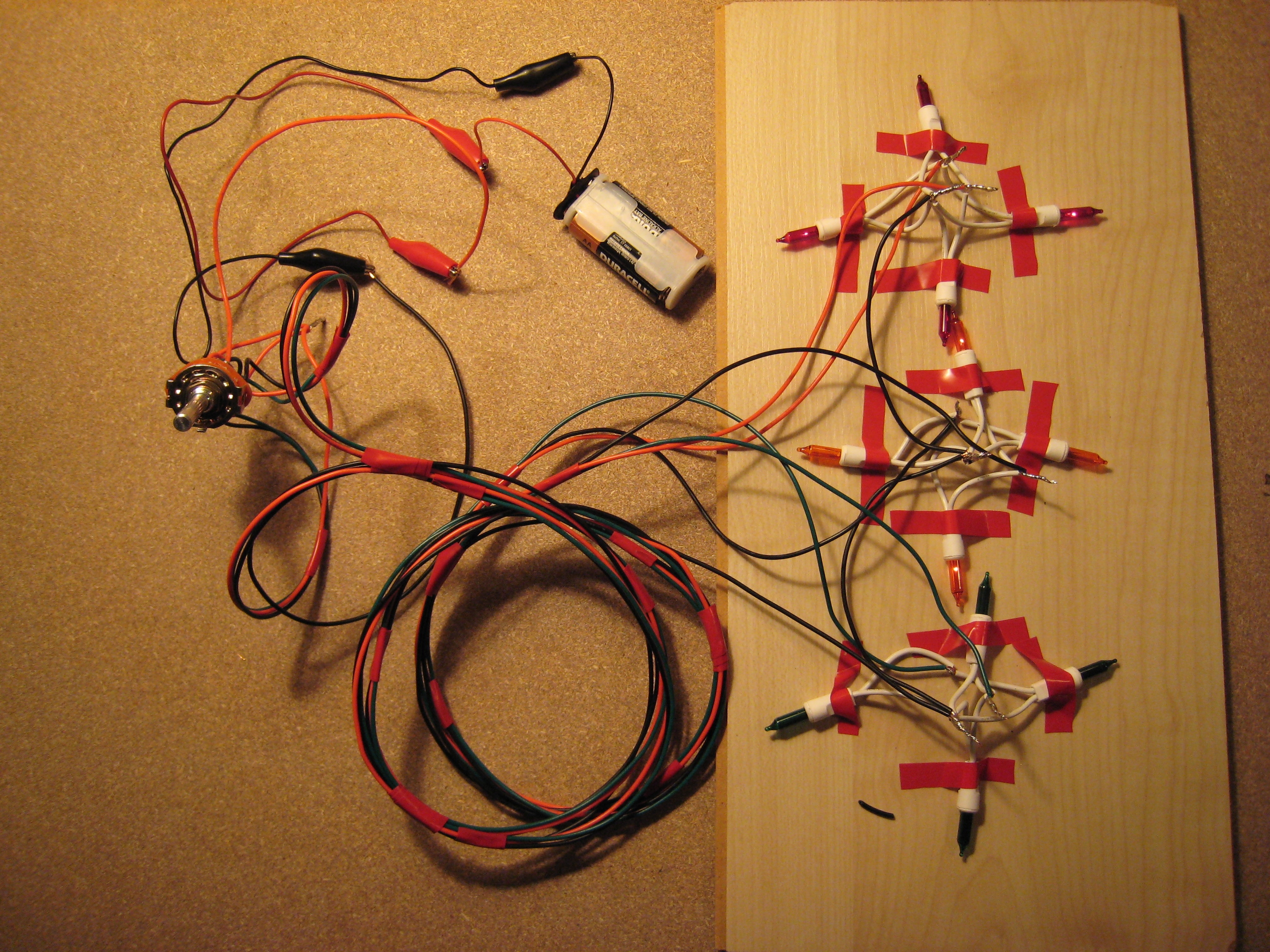
Figure 7. What started as a simple project got complex.
Overall, I was fairly satisfied with the stoplight, but am already making plans for a better one. It turned out that the rotary switch presented a number of challenges. One was that is was very hard for the kids to turn - they just couldn't get a tight enough grip on the shaft. I can fix this by putting a knob on the switch. The other problem is that the switch has a stop after position 6. I would have preferred a switch that could advance from position 6 back to position 1. I thought about cutting off the metal stop inside the switch, but decided against it because of the risk of breaking the switch that took so long to wire up.
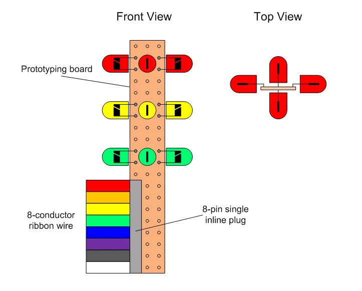
This may be getting out of hand. If I make another stoplight, I am going to place an emphasis on ease of assembly. I will probably use LEDs soldered directly onto a prototyping board as shown in figure 8. Instead of a complicated wiring harness, I'll use 8-conductor ribbon wire with a single inline plug.
Figure 8. An easier-to-assemble design.
I'll also replace the rotary switch with a simple sequencing circuit or perhaps a micro-controller such as a Basic Stamp. I like the micro-controller idea because I'd get to write software for features like flashing red, sequenced lights, and even pressure sensors. If I do this I'm sure you will read about it here.
Have a wonderful holiday and a happy New Year.
-Mike